Laser continuous cutting device having dedusting function

A cutting device and laser technology, used in laser welding equipment, manufacturing tools, welding equipment, etc., can solve the problems of backing plate pollution, scratches, pole piece damage, etc., to improve production efficiency, reduce friction, and ensure safety. Effect

Active Publication Date: 2015-10-14
CONTEMPORARY AMPEREX TECH CO
View PDF6 Cites 23 Cited by
  • Summary
  • Abstract
  • Description
  • Claims
  • Application Information

AI Technical Summary

Problems solved by technology

[0005] First, since the processing mode is continuous feeding, the adsorption of the pole piece on the surface of the cutting backing plate will cause friction of the active material on the surface of the pole piece, causing damage to the pole piece, scratches, affecting the performance of the battery, and even affecting the safety of the battery in severe cases
[0006] Second, the backing plate is quickly polluted and requires frequent replacement and cleaning, which is time-consuming and labor-intensive
[0007] Third, since the tension of the pole piece mainly depends on the tension effect, the vibration of the pole piece is also caused by the tension fluctuation. During the continuous feeding process of the pole piece, there is relative movement between the pole piece and the cutting backing plate. The cutting pads are suspended in the air, giving the pole piece a vibration space, making the vibration of the pole piece out of focus and affecting the laser cutting effect

Method used


Image

  • Laser continuous cutting device having dedusting function
  • Laser continuous cutting device having dedusting function
  • Laser continuous cutting device having dedusting function

Examples


Embodiment Construction

[0029] The present invention and its beneficial effects will be further described in detail below with reference to the specific embodiments and the drawings of the specification, but the specific embodiments of the present invention are not limited thereto.

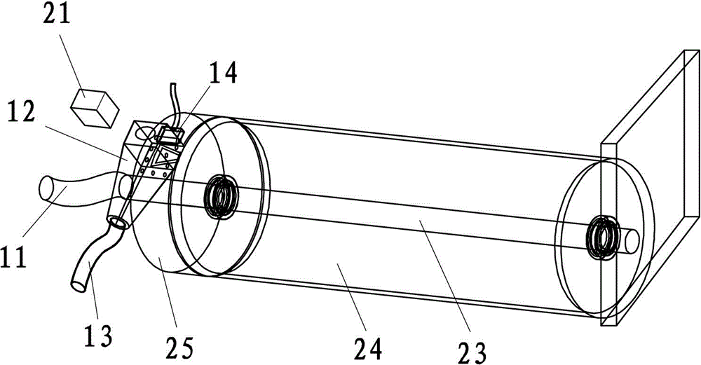
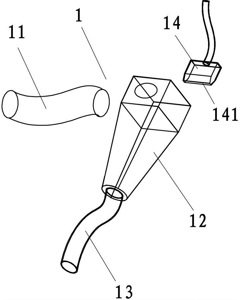
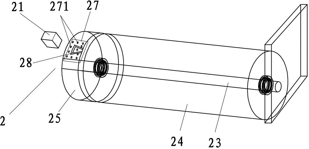
[0030] Such as Figure 1 to 4 As shown, a laser continuous cutting device with dust removal function includes a dust removal mechanism 1 and a laser cutting mechanism 2. The laser cutting mechanism 2 includes a laser head 21 and a pedestal assembly 22. The pedestal assembly 22 includes a central shaft 23 and a rotating roller 24 And the fixed roller 25. The rotating roller 24 and the fixed roller 25 have the same radius. The fixed roller 25 is connected with the rotating roller 24 through the central shaft 23. There is a distance 26 between the fixed roller 25 and the rotating roller 24 corresponding to the cutting path of the laser head 21. The size of the gap 26 is adjustable from 1mm to 5mm. The fixed roller 25 is fixe...


PUM


Abstract

The invention belongs to the technical field of laser cutting and particularly relates to a laser continuous cutting device having a dedusting function. The laser continuous cutting device comprises a dedusting mechanism and a laser cutting mechanism. The laser cutting mechanism comprises a laser head and a cushion seat module. The cushion seat module comprises a center shaft, a rotating roller and a fixed roller. The rotating roller and the fixed roller have the same radius, the fixed roller is connected with the rotating roller through the center shaft and is fixed relative to the center shaft, and the rotating roller can rotate relative to the center shaft. When a pole piece is cut, the pole piece adheres to the rotating roller by means of tension provided by mechanical transmission during the feeding, and a to-be-cut pole lug reserved area on the pole piece adheres to the fixed roller. The linear velocity of the rotating roller and the feeding speed of the pole piece are the same, so that no sliding friction occurs between the pole piece and the rotating roller, and the damage to the pole piece caused by the sliding friction between the pole piece and the rotating roller is avoided.

Description

Technical field [0001] The invention belongs to the technical field of laser cutting, and specifically relates to a laser continuous cutting device with a dust removal function. Background technique [0002] In recent years, the application of lithium-ion batteries has become more and more extensive, and the increasing market demand has promoted the development of lithium-ion battery manufacturing. Among them, in the battery production process, its tabs can be welded or laser cut. obtain. Compared with laser cutting pole pieces, the method of welding pole ears is prone to false welding, and the stability and reliability are relatively low. The process of laser cutting the pole piece will produce dust. If the dust adheres to the pole piece roll material and is brought into the subsequent process, or even caught inside the battery, it will easily pierce the isolation film in the battery cell and cause the battery to micro Short circuit may even lead to safety hazards such as ba...

Claims


Application Information

Patent Timeline
Patent Type & Authority Applications(China)
IPC IPC(8): B23K26/38B23K26/142B23K26/70B23K26/16
CPCB23K26/16B23K26/38B23K2101/36
Inventor 江桦锐陈木贵余深华方宏新何平
Owner CONTEMPORARY AMPEREX TECH CO
Why Eureka
Try Eureka