

Double-shaft rack opposed engine
A technology of engines and shaft teeth, which is applied in the field of engines, can solve the problems of complex structure of crankshaft engines, unstable power transmission, heavy weight, etc., and achieve the effects of compact structure, high work efficiency and small vibration
Inactive Publication Date: 2015-10-14
孙书伟
View PDF0 Cites 12 Cited by
- Summary
- Abstract
- Description
- Claims
- Application Information
AI Technical Summary
Problems solved by technology
[0003] In order to solve the shortcomings of the old product crankshaft engine with complex structure, heavy weight, large volume, large loss, low efficiency, and unstable power transmission
Method used
View moreImage
Smart ImageViewing Examples


Examples
Embodiment Construction
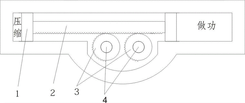
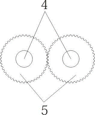
[0007] Double-shaft rack-and-rack engine, the four combustion chambers run the intake, compression, power, and exhaust strokes in sequence. Under the constraints of the double-shaft gear set, the two half-circle gears are alternately connected to the racks of the connected pistons. , convert the back and forth movement of the rack into a circular motion, and output power.
Login to View More PUM
 Abstract
The invention relates to a double-shaft rack opposed engine which is used for providing power for automobiles, ships and the like. The double-shaft rack opposed engine aims to overcome the defects that old product crankshaft engines are complex in structure, high in weight, large in size, large in loss, low in efficiency and instable in power transmission. According to the technical scheme adopted by the double-shaft rack opposed engine, a crankshaft and a flywheel of a traditional engine are omitted, and innovative racks, pistons, gear sets and semicycle gears are adopted. Movement of the pistons is transmitted to a gear structure through the racks, the semicycle gears and the racks / gears work alternately, and back-and-forth movement of the racks is changed into circumferential movement. The structure is simplified; the weight is lowered, and the size is reduced; friction is reduced; the service life is prolonged; vibration is small and noise is low. Particularly, power arms of the gears are equal, the power, torque and speed are output linearly, in this way, the stability is extremely high, and the acting efficiency is high. The double-shaft rack opposed engine overcomes the defects that the power arms of the crankshaft of the traditional crankshaft engine change continuously, the power, torque and speed are output in a pulsed mode, in this way, the stability is extremely poor, and the acting efficiency is low.
Description
technical field [0001] The present invention relates to: a kind of engine, is used as the power device of automobile, ship etc. Background technique [0002] At present, the engine used is the crankshaft engine invented decades ago. Although the technology is mature, it is too old and there is no room for improvement. The structure is complex, heavy, bulky, difficult to process, and the friction loss of the crankshaft is large. Because the crankshaft power arm is constantly changing, the output of power, torque, and speed is pulsed, which is very unstable and has low work efficiency. Contents of the invention [0003] In order to solve the shortcomings of the old product crankshaft engine with complex structure, heavy weight, large volume, large loss, low efficiency, and unstable power transmission. The technical solution adopted by the invention is: the crankshaft of the traditional engine is canceled, the structure is simplified, and the weight and volume are greatly re...
Claims
Login to View More Application Information
Patent Timeline
 IPC IPC(8): F02B75/32F02B75/24
Inventor孙书伟
Owner孙书伟