
A heating plate structure

A heating plate, heat dissipation mesh plate technology, applied in ohmic resistance heating, electric heating devices, electrical components, etc., can solve the problems of unsatisfactory snow melting and deicing effect, damage to road performance, low intelligence, etc., to reduce costs and construction. The effect of difficulty, low production cost and firm structure

Inactive Publication Date: 2017-04-05
浙江鼎栎家居有限公司
View PDF5 Cites 0 Cited by
  • Summary
  • Abstract
  • Description
  • Claims
  • Application Information

AI Technical Summary

Problems solved by technology

[0002] The existing commonly used road surface snow melting and deicing methods mainly include manual or mechanical removal method, snow melting agent method, etc. The effect of snow melting and deicing is not ideal, and snow can only be melted when there is ice and snow on the road surface, and it cannot be used when ice and snow accumulate on the road. prevention before pavement
The most commonly used deicing agent can also damage the performance of the existing pavement, and has problems such as slow melting speed, low intelligence, low efficiency, and high energy consumption.

Method used


Image

  • A heating plate structure
  • A heating plate structure
  • A heating plate structure

Examples


Embodiment 1

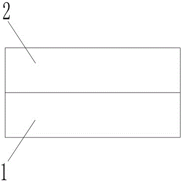
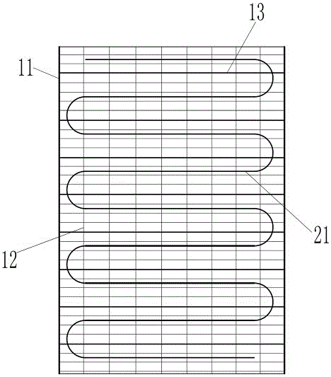
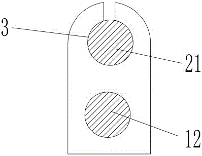
[0036] A heating plate structure includes a heat dissipation mesh layer 1, a heating wire layer 2 laid on the heat dissipation mesh layer, and a plurality of connecting units for connecting the heat dissipation mesh layer and the heating wire layer are provided on the heat dissipation mesh layer , The heating wire layer includes at least one heating wire 21 arranged on the heat dissipation net plate layer, and the connecting monomer is provided with a fixing clip ring 3 for clamping the heating wire at least to form the The network cable of the heat dissipation screen layer is a metal network cable.

[0037] The heat dissipation screen layer includes two layers of flexible and curlable heat dissipation screens, the heating wire is sandwiched between the two heat dissipation screens, and the network wires of the heat dissipation screen include parallelly arranged on both sides of the heat dissipation screen. The shaped reinforced frame wire 11 and the main grid line 12 interlacedl...

Embodiment 2

[0040] The difference from the above embodiment is that the heat dissipation mesh layer includes a single layer of flexible and curlable heat dissipation mesh, the heating wire layer is two layers provided on both surfaces of the heat dissipation mesh, and the heat dissipation mesh The network cables of the board include shaped reinforced frame cables 11 arranged in parallel on both sides of the heat dissipation screen and main grid lines 12 interlaced between two shaped reinforced frame cables. The diameter of the shaped reinforced frame cables is larger than that of the main grid cables. diameter. Both sides of the connecting unit are provided with a fixing clamp ring with openings, and the middle part is a fixing section fixed on the wire of the heat dissipating net plate layer by heat fusion, and the heating wire located on both sides of the heat dissipating net plate They are respectively pierced in the fixing clip ring on both sides of the connecting monomer.

Embodiment 3

[0042] The difference from the above-mentioned embodiment is that the connecting unit is provided with an open fixing clip ring, and a part of the heating wire and the local wire of the heat dissipation mesh layer are passed through the fixing clip ring.


PUM


Abstract

The invention belongs to the field of heating devices, and especially relates to a heating structure that can be arranged in a wall or a road body. The heating structure comprises a radiator grid layer, a heating wire layer laid on the radiator grid layer, and a plurality of connecting units for connecting the radiator grid layer and the heating wire layer are arranged on at least one surface of the radiator grid layer. The heating wire layer comprises at least one heating wire arranged on the radiator grid layer, and a fixing clamping ring for at least clamping the heating wire is arranged on each unit. The wires forming the radiator grid layer are metallic wires. Heat radiation can be rapidly carried out for the heating wires in the heating wire layer after being heated through the radiator grid layer, the heat radiation area is increased, and the heat radiation efficiency is improved. Especially, when the heating wires are sealed in a wall or a road body, and the concrete and cement with poor thermal conductivity wrap up the heating plate, the radiator grid layer formed by metallic wires greatly improves heat radiation efficiency.

Description

Technical field [0001] The invention belongs to the field of heating devices, and particularly relates to a heating structure that can be arranged in a wall or a road. Background technique [0002] The existing commonly used methods of snow melting and deicing on roads mainly include manual or mechanical removal, spraying deicing agents, etc. The effect of snow melting and deicing is not ideal, and snow can only be melted when ice and snow appear on the road. Prevent before the pavement. The most commonly used snow melting agent will also damage the performance of the existing road surface, and have problems such as slow snow melting speed, low intelligence, low efficiency, and high energy consumption. Summary of the invention [0003] The purpose of the present invention is to provide a new road body structure with a high degree of intelligence, which can completely solve road freezing and prevent road freezing from the above problems. [0004] The above technical objectives of t...

Claims


Application Information

Patent Timeline
Patent Type & Authority Patents(China)
IPC IPC(8): H05B3/22E01H5/10
Inventor 何家忠杨杰
Owner 浙江鼎栎家居有限公司
Learn More