Microwave ablation antenna with internally-arranged pipelines

A technology of microwave ablation and internal pipeline, which is applied in the direction of trocars, medical instruments, and parts of surgical instruments, etc. It can solve tumor coagulation necrosis or local hemostasis, increase surgical trauma and clinical risk, and microwave ablation antenna function Single and other problems, to achieve the effect of reducing the trauma and risk of treatment, reducing the degree of coking, and reducing the number of punctures

Inactive Publication Date: 2015-10-21
CANYON MEDICAL INC
View PDF6 Cites 9 Cited by
  • Summary
  • Abstract
  • Description
  • Claims
  • Application Information

AI Technical Summary

Problems solved by technology

[0004] However, the existing microwave ablation antenna still has the following disadvantages: the current microwave ablation antenna has a single function, and can only achieve th

Method used


Image

  • Microwave ablation antenna with internally-arranged pipelines
  • Microwave ablation antenna with internally-arranged pipelines
  • Microwave ablation antenna with internally-arranged pipelines

Examples


Embodiment 1

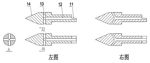
[0035] Such as image 3 As shown in the left figure, the microwave radiation antenna head 1 of this case is composed of a step 11 , a central pipe 12 , a side through hole 13 , and an antenna tip 14 . The step 11 is used for welding the microwave radiation antenna head 1 and the transmission cable 4 , and the central pipe 12 of the microwave radiation antenna head 1 communicates with each side through hole 13 of the antenna tip 14 . The number of side through holes 13 can be four, six, eight, etc. The side through holes 13 can be perpendicular to the central pipe 12, and can also be arranged at a certain angle with the central pipe 12, such as image 3 Shown on the right. The microwave radiation antenna head 1 is made of high-strength and high-conductivity medical alloy material, the surface is roughened, and sprayed with high-temperature-resistant and anti-sticking materials. The main function of the antenna tip 14 is to puncture. In order to improve the sharpness of the p...

Embodiment 2

[0040] The implementation mode of this case is different from the implementation example 1 except that the following description is different from the implementation example 1, and the others are the same.

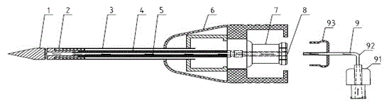
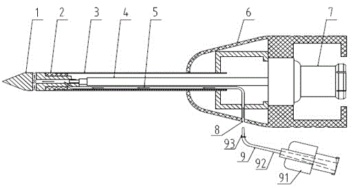
[0041] The microwave radiation antenna head 1 of this case is made up of step 11, central pipe 12, side through hole 13, antenna tip 14, inner pipe side connection hole 15, as Figure 4 shown. The microwave radiation antenna head 1 of this case increases the inner pipe side connection hole 15, one end of the inner pipe 5 is connected to the inner pipe side connection hole 15, and the other end is connected to the pipe outer interface 8, as figure 2 shown. In this case, the inner pipe 5 adopts a special pipe, which is independent of the microwave transmission cable 4 , and is arranged between the microwave transmission cable 4 and the inner hole of the antenna rod 3 , and is led out from the side of the handle 6 through the pipe outer interface 8 . Inner pipeline 5 can u...


PUM


Abstract

The invention discloses a microwave ablation antenna with internally-arranged pipelines. The microwave ablation antenna with the internally-arranged pipelines comprises a microwave radiation antenna head 1, a matched insulation sleeve 2, an antenna mast 3, a microwave transmission cable 4, a handle and a coaxial connector 7. The inner pipeline 5 in the antenna mast 3 is communicated with the center pipeline 12 and a side through hole 13 in the microwave radiation antenna head 1. One end of the inner pipeline 5 is in butt joint with the center pipeline 12 and the other end of the inner pipeline 5 is an outer pipeline joint 8 located on the handle 6. The side through hole 13 is located on the side face of the microwave radiation antenna head 1. The injection function of the ablation antenna is achieved through the outer pipeline joint 8 via the inner pipeline 5, the center pipeline 12 and the side through hole 13. Living tissue cells are extracted through the side through hole 13 on the microwave radiation antenna head 1 into the center pipeline 12, the inner pipeline 5 and the outer pipeline joint 8.

Description

technical field [0001] The present invention relates to a multifunctional microwave ablation antenna in the medical field, in particular to a hollow pipe with one or more antenna heads connected therein, which is used for injecting anesthetics, chemotherapy drugs, chemical ablation drugs, and contrast agents during tumor ablation treatment , Extraction of living tissue cells and other functions of the microwave ablation antenna. Background technique [0002] Image-guided microwave ablation therapy has become a minimally invasive method for treating tumors. The microwave ablation antenna is punctured percutaneously into the tumor lesion. The microwave energy emitted by the microwave ablation therapy instrument is transmitted to the ablation antenna through the transmission cable, and the microwave energy is radiated to the tumor focus tissue by the ablation antenna. The ions and polar water molecules in the lesion tissue rotate and vibrate under the action of the microwave f...

Claims


Application Information

Patent Timeline
IPC IPC(8): A61B18/18A61B10/02A61M31/00
Inventor 叶欣江荣华房留琴柳伟杨霞
Owner CANYON MEDICAL INC
Why Eureka
Try Eureka