
Method for calculating reflected light intensity of cubic pyramid type retroflection material

A technology of reflected light intensity and retro-reflection, used in optics, optical components, instruments, etc., can solve problems such as light energy loss, and achieve high accuracy and reliability.

Inactive Publication Date: 2015-10-21
SOUTHWEAT UNIV OF SCI & TECH
View PDF3 Cites 5 Cited by
  • Summary
  • Abstract
  • Description
  • Claims
  • Application Information

AI Technical Summary

Problems solved by technology

In other words, those light rays that are not reflected by the three reflective surfaces in turn and go out to other directions in advance will deviate from the retroreflective light path and cause light energy loss. This part of light energy loss is reflected in the effective reflection section of the reflective unit
(2) Reflection and refraction loss. On the one hand, it is reflection loss. When light enters and exits the front surface of the reflective film, part of the light is reflected and deviates from the main optical path, resulting in light energy loss; on the other hand, it is refraction loss. Due to the change of the direction of incident light, Especially when the incident angle becomes larger, the total reflection condition of the light in the reflection process may no longer be satisfied. At this time, it is inevitable to generate refracted light, which escapes from the back of the reflective film and causes light energy loss.

Method used


Image

  • Method for calculating reflected light intensity of cubic pyramid type retroflection material
  • Method for calculating reflected light intensity of cubic pyramid type retroflection material
  • Method for calculating reflected light intensity of cubic pyramid type retroflection material

Examples


Embodiment 1

[0061]Embodiment 1——complete cube-pyramid array structure, the light vector is perpendicular to the incident surface

[0062] The relative light intensity R of reflected light is the ratio of reflected light to incident light intensity, which reflects the energy loss of monochromatic polarized light after multiple reflections and refractions of cube pyramid units. When the cube pyramid unit array and the polarization state of the incident light are determined, R is the propagation direction of the incident light The function.

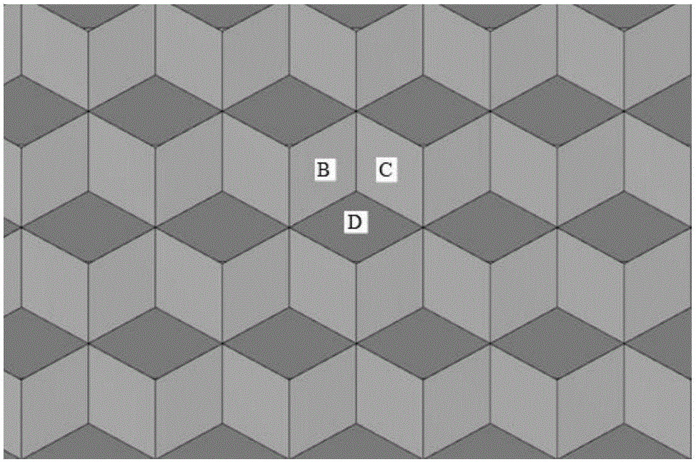
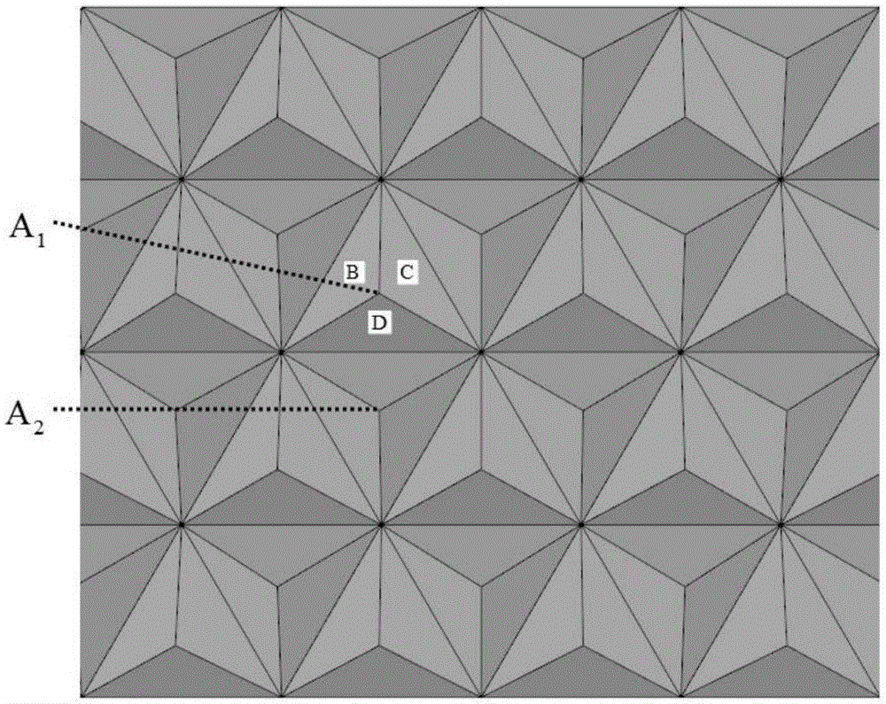
[0063] The reflector structure is a cube-pyramid unit array of complete pyramids, such as figure 1 shown. The matrix material is polycarbonate, n=1.59. The incident light is completely polarized light, and the vibration direction of the light vector is perpendicular to the incident surface (o light). The changes are shown in Image 6 .

[0064] It can be seen from the results in the figure that: (1) There are three orientations that form an angl...

Embodiment 2

[0065] Embodiment 2——Complete Cube Pyramid Array Structure, Light Vector Parallel to Incident Surface

[0066] The reflector structure is a cube-pyramid unit array of complete pyramids, such as figure 1 shown. The matrix material is polycarbonate, n=1.59. The incident light is completely polarized light, and the vibration direction of the light vector is parallel to the incident surface (e light). changes, such as Figure 8 shown.

[0067] It can be seen from the calculation results that: (1) There are three orientations that form an angle of 120° with each other, and the relative light intensity in these three orientations maintains a large value and decreases slowly with the increase of the incident angle. The azimuth angles of these three special azimuths are: 30°, 150°, 270°. (2) Different from Example 1, the relative intensity R of reflected light in the above three special directions first increases (the maximum value is 100%) and then decreases, and remains almost...

Embodiment 3

[0068] Embodiment 3——Complete cubic pyramid array structure, illuminated by natural light

[0069] The relative light intensity R of the reflected light is the ratio of the retroreflected light intensity to the incident light intensity, which reflects the energy loss of monochromatic linearly polarized light after multiple reflections and refractions of the cube pyramid unit. When the cube pyramid array structure is determined, R is the propagation direction of the incident light and the vibration direction of the light vector The function.

[0070] When using retroreflective materials, usually the lighting source is a common light source that emits natural light. When the propagation direction is given, natural light can be regarded as composed of multiple beams of linearly polarized light whose vibration directions are randomly and uniformly distributed and have no fixed phase relationship with each other. In this paper, the following formula is used to simulate the relat...


PUM


Abstract

The invention relates to a method for calculating a reflected light intensity of a cubic pyramid type retroflection material. The method comprises: (1), designing a cubic pyramid type structure; (2), carrying out five steps to realize incident light conversion into retroreflection light; and (3), compiling a calculation flow of the relative intensity of the retroreflection light. According to the invention, accurate calculation is carried out to obtain reflected light intensity distribution of the cubic pyramid type retroflection materials with various structures and the reflected light intensity distribution reflects the retroflection performances of the materials. The method can be used for evaluation of the novel retroflection material performance; and the design of the novel retroflection material optimization structure can be assisted; links of tested manufacturing and testing in the novel material design are saved or reduced; the development expenses are saved; and the development flow is shortened.

Description

technical field [0001] The invention relates to a method for calculating the reflected light intensity of a retro-reflective material, in particular to a method for calculating the reflected light intensity of a cube-corner retro-reflective material. Background technique [0002] Retroreflection, also known as retroreflection, is a special reflection phenomenon. No matter in which direction the light is incident, the reflected light always propagates against the incident light path. The characteristics of retroreflection are widely used in communication, remote sensing and telemetry, photography, stage scenery and other fields, especially widely used in the production of various warning signs, such as danger warning signs on the road, traffic control signs, navigation signs, billboards, license plates, Warning signs on various professional uniforms, etc. All kinds of reflective signs made of retro-reflective characteristics make full use of the light of the vehicle itself d...

Claims


Application Information

Patent Timeline
Patent Type & Authority Applications(China)
IPC IPC(8): G02B5/122G02B5/124
CPCG02B5/122G02B5/124G02B27/0012
Inventor 罗雰郭志成袁长迎
Owner SOUTHWEAT UNIV OF SCI & TECH
Learn More