Multi-rotor aircraft and control method thereof

A multi-rotor aircraft and motor control technology, applied in the field of flight, can solve the problems of low motor efficiency, easy rollover, small number of axes, etc., and achieve the effect of increasing the maximum load

Inactive Publication Date: 2015-10-28
杨小韬
View PDF8 Cites 9 Cited by
  • Summary
  • Abstract
  • Description
  • Claims
  • Application Information

AI Technical Summary

Problems solved by technology

[0017] Many small 4-rotor aircraft have low motor efficiency, small pulling force, and low maximum take-off weight. The battery has already accounted for more than 25% of the total weight, and cannot carry a larger capacity battery. The stop time is about 20 minutes
And if in the actual use process, if the maneuvering time is long or the wind is strong, the hovering time will be shorter, even less than 10 minutes, which greatly limits the application of the aircraft
Although 6-rotor and 8-rotor aircraft can use large-scale motors and blades with high efficiency to increase the pulling force to carry more equipment and batteries, in order to achieve better stability and maneuverability, large multi-rotor aircraft are extremely power-consuming to operate , the actual use time is not greatly improved compared with small aircraft
[0023] The two propellers of the 2-rotor aircraft have opposite rotation directions. By offsetting the torque, it can ensure that the horizontal plane does not spin, but the distribution of mass and moment is basically in a straight line, and it is easy to roll over. Generally speaking, there are no 4, 6, and 8 rotor aircraft. Stablize
[0025] In general, multi-rotor aircraft with less than 4 rotors require auxiliary devices other than electronic governors to complete their balance and controllability, which increases the complexity of the structure. Once the auxiliary devices fail, the aircraft is likely to lose control and crashed
At the same time, due to the small number of shafts, the lift provided by a single propeller is limited, and it cannot provide a large amount of additional lift for other purposes, and the power redundancy is small. If one shaft fails, there is basically no way to compensate for the lost lift.

Method used


Image

  • Multi-rotor aircraft and control method thereof
  • Multi-rotor aircraft and control method thereof
  • Multi-rotor aircraft and control method thereof

Examples


Embodiment Construction

[0045] In order to make the object, technical solution and advantages of the present invention clearer, the present invention will be further described in detail below in conjunction with the accompanying drawings and embodiments. It should be understood that the specific embodiments described here are only used to explain the present invention, not to limit the present invention.

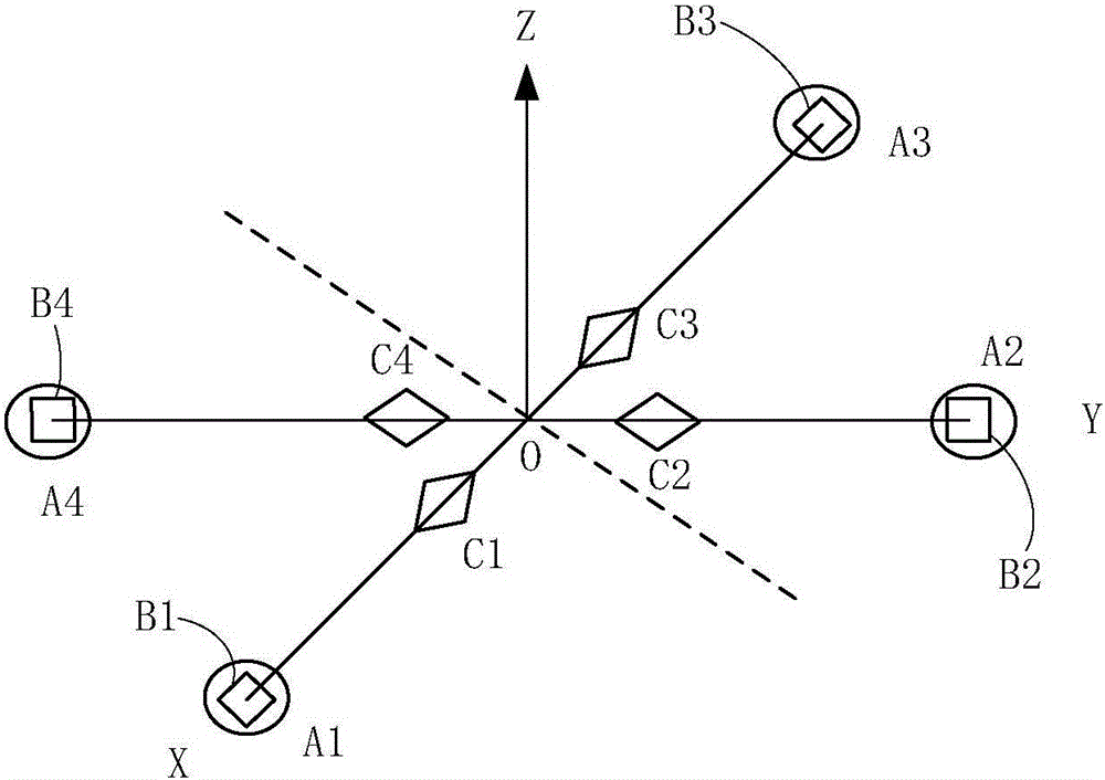
[0046] In addition, the technical features involved in the various embodiments of the present invention described below can be combined with each other as long as they do not constitute a conflict with each other. The motor referred to in the present invention refers to the DC brushless motor used to rotate the propeller, and can also be other types of motors used to drive the propeller; the wheelbase referred to in the present invention refers to the axial center distance of the symmetrical motor; The multi-rotor aircraft referred to in the present invention includes aircrafts including 4, 6, and ...


PUM


Abstract

The invention relates to a multi-rotor aircraft and a control method thereof. The multi-rotor aircraft comprises a plurality of propellers and a plurality of motors. Each motor drives the corresponding propeller to rotate. The multi-rotor aircraft further comprises a plurality of adjustable devices and micro-control motors for controlling the adjustable devices. The adjustable devices are arranged within the range of downward flushing air flow generated by the propellers and interact with the downward flushing air flow to generate new torque in the specific direction. The micro-control motors are used for controlling the adjustable devices to control the torque formed by the adjustable devices. According to the multi-rotor aircraft, the adjustable devices are introduced to interact with the air flow of the propellers so as to generate extra acting force, the new torque generated in this way and the torque formed by the propellers act at the same time, and therefore the maximum load, the controllability, the stability, the maneuverability, the runtime, the safety performance and other performance of the aircraft are synchronously improved.

Description

【Technical field】 [0001] The invention relates to the technical field of flight, in particular to a multi-rotor aircraft and a control method thereof. 【Background technique】 [0002] The structure of multi-rotor aircraft tends to be simpler, the cost is relatively low, and the performance and flight control technology are getting more and more perfect. It has broad application prospects and has become a popular hot spot in the world. [0003] The power system of the multi-rotor aircraft mainly includes batteries, motors, propellers and electronic governors, and with various sensors and flight control software, the current of the motors is adjusted through the electronic governors, thereby adjusting the speed of the motors, so that the propellers generate The pulling force and the moments in all directions can realize the control of take-off, landing and other flight attitudes of the multi-rotor aircraft. [0004] At present, multi-rotor aircraft, whether it is 4-rotor, 6-ro...

Claims


Application Information

Patent Timeline
Patent Type & Authority Applications(China)
IPC IPC(8): B64C27/08B64C27/82
Inventor 杨小韬
Owner 杨小韬
Why Eureka
Try Eureka