
Cathode center layout of Hall thruster

A Hall thruster and cathode technology, applied in the field of plasma, can solve the problems of unsatisfactory beam neutralization effect, difficult satellite space plume protection, affecting the overall efficiency of the thruster, etc., so as to increase the effective voltage of the anode and increase the coupling effect, the effect of improving efficiency

Inactive Publication Date: 2015-10-28
LANZHOU INST OF PHYSICS CHINESE ACADEMY OF SPACE TECH
View PDF9 Cites 10 Cited by
  • Summary
  • Abstract
  • Description
  • Claims
  • Application Information

AI Technical Summary

Problems solved by technology

The main problems are as follows: (1) Since the cathode is arranged outside the discharge chamber, the electrons emitted by the cathode cannot evenly enter the discharge channel, and the coupling voltage between the cathode and the discharge chamber is high, which affects the overall efficiency of the thruster; (2) due to The position of the cathode deviates from the central axis of the discharge chamber, and the beam neutralization effect is not ideal, which brings certain difficulties to satellite space plume protection

Method used


Image

  • Cathode center layout of Hall thruster
  • Cathode center layout of Hall thruster
  • Cathode center layout of Hall thruster

Examples


Embodiment Construction

[0017] The present invention will be described in detail below with reference to the accompanying drawings and examples.

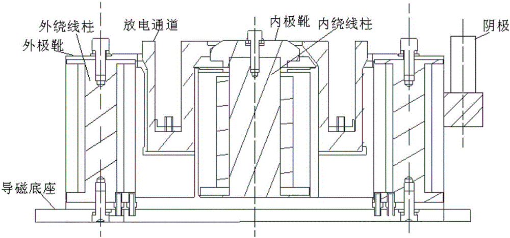
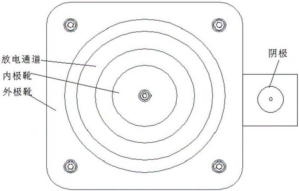
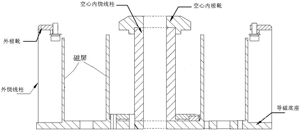
[0018] The invention provides a cathode center layout of a Hall thruster. The structure of the existing Hall thruster is as follows: figure 1 As shown, it includes inner pole shoe, inner winding post, discharge channel, outer pole shoe, outer winding post, magnetic permeation base and cathode, wherein the cathode is composed of a cylindrical cathode main body structure and supporting parts, and the present invention arranges the cathode In the center of the Hall thruster, the symmetrical layout of the cathode structure is realized. The electrons emitted by the cathode can enter the discharge channel evenly, and at the same time, the original electrons emitted are located in the center of the beam to achieve beam ion neutralization more uniformly. The specific structure is as Figure 3 ~ Figure 5 As shown, it specifically includes the following steps:

...


PUM


Abstract

The invention discloses a cathode center layout of a Hall thruster. By means of the cathode center layout, the uniformity of plasma in a discharge channel can be improved, the coupling voltage between a cathode and a discharge chamber is reduced, plume neutral loss energy is reduced, and the efficiency of the thruster is effectively improved finally. A cylindrical cavity penetrating through an inner winding column and an inner pole shoe is formed in the inner winding column and the inner pole shoe of an existing Hall thruster structure along the center axis of the Hall thruster first; afterwards, the ampere turns of coils on the inner winding column and an outer winding column of the Hall thruster are adjusted till a magnetic field meeting the requirement of a discharge chamber channel of the Hall thruster is obtained, and the magnetic field of the inner winding column is in an unsaturation state; and finally, a cylindrical cathode body structure is placed in a cavity of the inner winding column, and a ceramic sleeve is installed between the cathode and the cavity of the inner winding column.

Description

technical field [0001] The invention relates to the fields of aerospace technology and low-temperature plasma technology, in particular to a cathode center layout of a Hall thruster. Background technique [0002] The cathode is an important part of the Hall thruster. The electrons emitted by the cathode have two main functions. Some of the electrons enter the channel of the Hall thruster and are used to ionize the working fluid; the other part of the electrons recombine with the beam ions in the plume. , to ensure electrical neutrality in the plume region. A large number of experiments have shown that due to the coupling effect of the cathode and thruster discharge process, the installation position and angle of the cathode have a great influence on the discharge plasma characteristics, thrust macroscopic performance and beam neutralization characteristics of the Hall thruster. [0003] In the Hall thruster structure of the prior art, the cathode is placed outside the disch...

Claims


Application Information

Patent Timeline
IPC IPC(8): F03H1/00H05H1/02
Inventor 龙建飞张天平杨乐贾连军高俊
Owner LANZHOU INST OF PHYSICS CHINESE ACADEMY OF SPACE TECH
Learn More