System of utilizing light rays having angles therebetween to carry out displacement monitoring and measurement method thereof

An angled and measuring method technology, which is applied in the direction of using optical devices, measuring devices, instruments, etc., can solve the problems of inability to realize automatic real-time monitoring, increase transportation costs, and inability to eliminate manual errors, so as to achieve rich and reliable measurement results and reduce The number of manual return times and the effect of easy promotion

Active Publication Date: 2015-10-28
广州市地平线岩土工程有限公司 +2
View PDF8 Cites 4 Cited by
  • Summary
  • Abstract
  • Description
  • Claims
  • Application Information

AI Technical Summary

Problems solved by technology

However, this method is complicated to operate and cannot eliminate manual errors; each measurement requires professionals to set up instruments and monitor, which is highly dependent on manual work and has a high return rate
[0004] For monitoring objects located in remote areas, traditional monitoring methods require monitoring personnel to repeatedly travel to and from monitoring locations, which increases transportation costs and cannot achieve automatic real-time monitoring
In addition, for more dangerous monitoring objects, such as landslides in the accelerated deformation stage, traditional monitoring methods are likely to cause safety hazards and threaten personal safety.

Method used


Image

  • System of utilizing light rays having angles therebetween to carry out displacement monitoring and measurement method thereof
  • System of utilizing light rays having angles therebetween to carry out displacement monitoring and measurement method thereof

Examples


Embodiment Construction

[0032] The specific embodiments of the present invention will be described in further detail below in conjunction with the accompanying drawings, but this does not constitute any limitation to the present invention.

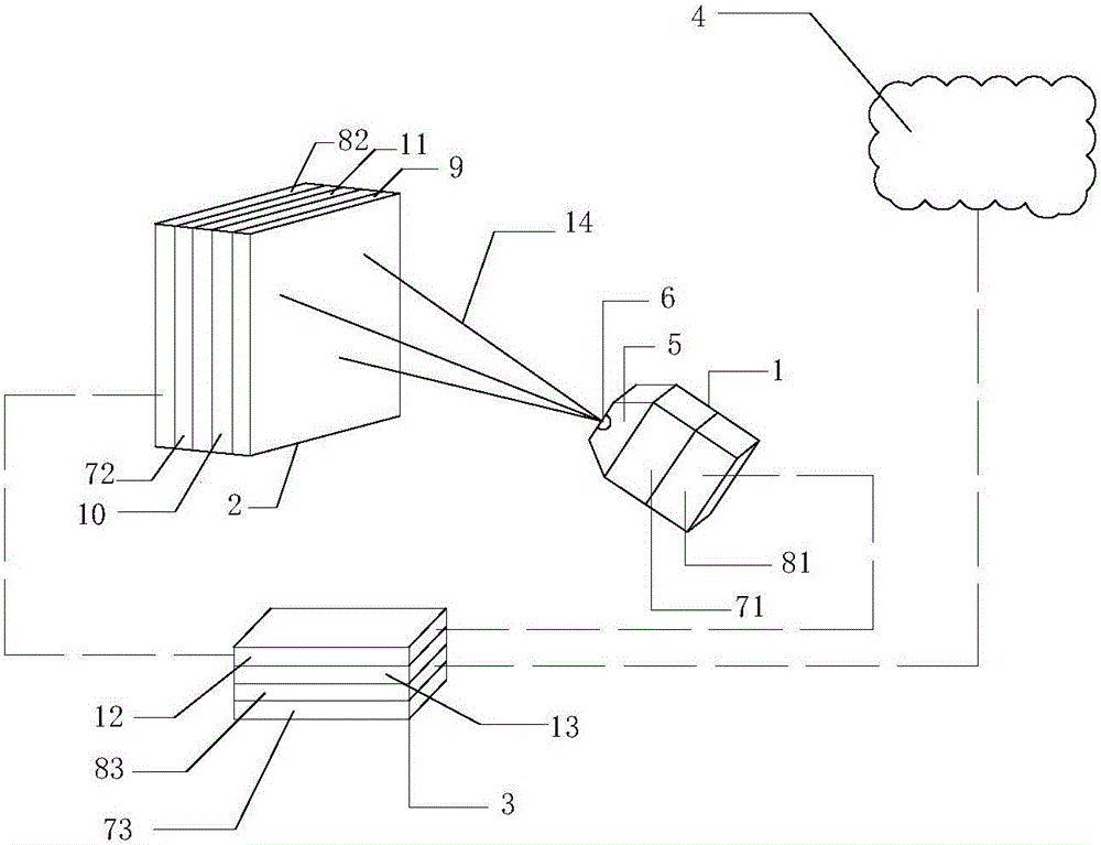
[0033] Such as figure 1 , 2 Shown:

[0034] A system that utilizes mutually angled light to monitor displacement changes is characterized in that it includes a light emitter 1, a light receiving target 2, a data collector 3, and a remote server 4; Angle of light 14, the light receiving target 2 is arranged on the monitoring point, and the light emitter 1 is installed on a stable position at a certain distance from the light receiving target 2, so that the three beams emitted by the light emitter 1 are mutually formed. The angled light rays 14 are directly irradiated on the light receiving target 2 .

[0035] In this embodiment, laser light is selected as the light emitted by the light emitter 1 .

[0036] The light emitter and the light receiving target are c...


PUM


Abstract

The present invention provides a system of utilizing light rays having angles therebetween to monitor displacement change. The system is characterized by comprising a light ray emitter, a light ray reception target, a data acquisition unit and a remote server, wherein the light ray emitter can emit three beams or multiple beams of light rays having angles therebetween, the light ray reception target is arranged at a monitoring point, and the light ray emitter is arranged at a stable position having a certain distance with the light ray reception target, so that the three beams or multiple beams of light rays having the angles therebetween and emitted by the light ray emitter can irradiate on the light ray reception target directly. The light ray emitter and the light ray reception target are connected with the data acquisition unit via a wireless local area network, the data acquisition unit transmits the displacement change condition to the remote server, and the remote server can store and analyze the data, and carries out the early warning on a monitoring value exceeding an engineering allowable value. The system and method of the present invention can realize the real-time monitoring and the early warning automation, enable the engineering safety to be improved and the personal error to be reduced, are high in monitoring precision and wide in monitoring range, and are convenient to popularize.

Description

technical field [0001] The invention relates to the fields of civil engineering, geological engineering and geological disaster monitoring, in particular to a system and method for monitoring displacement changes by using mutually angled light rays. technical background [0002] At present, in a large number of engineering practices in civil engineering, geological engineering, and disaster prevention and control, it is necessary to monitor the characteristics of displacement changes on the surface of rock and soil or engineering structures. For rock-soil masses or engineering structures with large deformation or accelerated deformation, real-time monitoring and early warning must be realized, so as to effectively prevent accidents and disasters. At the same time, it is also necessary to monitor the deformation state of the rock and soil mass or building structures that are being reinforced and processed in real time, so as to grasp the construction effect and ensure the saf...

Claims


Application Information

Patent Timeline
Patent Type & Authority Applications(China)
IPC IPC(8): G01B11/02
Inventor 赵其华李慧生赖光程
Owner 广州市地平线岩土工程有限公司
Why Eureka
Try Eureka