Low-power magnetic resistance sensor based on LTCC technology and preparation method therefor

A magnetoresistive sensor, low power consumption technology, applied in the direction of instruments, measuring magnetic variables, manufacturing measuring instruments, etc., can solve the problems of photolithography, increased coating times, high energy consumption, and increased difficulty of sensors, etc., to achieve easy large-scale Realize, simplify the preparation process, and improve the effect of the magnetic field

Active Publication Date: 2015-10-28
UNIV OF ELECTRONICS SCI & TECH OF CHINA
View PDF6 Cites 9 Cited by
  • Summary
  • Abstract
  • Description
  • Claims
  • Application Information

AI Technical Summary

Problems solved by technology

However, this method increases the number of photolithography and coating, and increases the difficulty of sensor preparation; in addition, the set/reset operation will...

Method used


Image

  • Low-power magnetic resistance sensor based on LTCC technology and preparation method therefor
  • Low-power magnetic resistance sensor based on LTCC technology and preparation method therefor
  • Low-power magnetic resistance sensor based on LTCC technology and preparation method therefor

Examples


preparation example Construction

[0032] A method for preparing a low-power magnetoresistive sensor based on LTCC technology provided by the invention, specifically comprises the following steps:

[0033] Step 1: Select non-magnetic LTCC microwave dielectric material as the casting substrate material, and use LTCC technology to make n-layer green ceramic tape diaphragm as the substrate;

[0034] Step 2: using silver paste to prepare the bottom coil by screen printing on the substrate obtained in step 1, and then preparing a green ceramic tape diaphragm on the bottom coil as the first green ceramic tape layer;

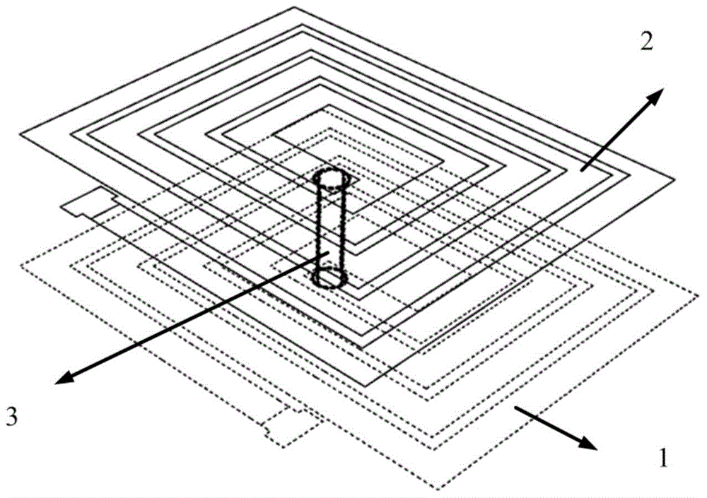
[0035] Step 3: Use silver paste to screen-print the top-layer coil on the first raw ceramic tape layer obtained in step 2, and connect the top-layer coil to the top-layer coil through the metal through hole in the center of the coil (using silver paste) to form a double-layer coupling layer of set / reset coils, such as figure 1 shown;

[0036] Step 4: Use LTCC technology to prepare 1-2 layers of green ...

Embodiment

[0040] A method for preparing a low-power magnetoresistive sensor based on LTCC technology, specifically comprising the following steps:

[0041] Step 1: Select Al 2 o 3 The LTCC material compounded with glass is used as the casting substrate material. Using LTCC technology, first stack about 400 μm green ceramic tape diaphragm to obtain the substrate;

[0042] Step 2: Use silver paste screen printing on the substrate obtained in step 1 to obtain the bottom coil, and then laminate a green ceramic tape diaphragm with a thickness of about 10 μm on the bottom coil as the first green ceramic tape layer ;

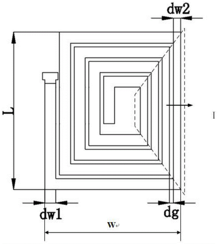
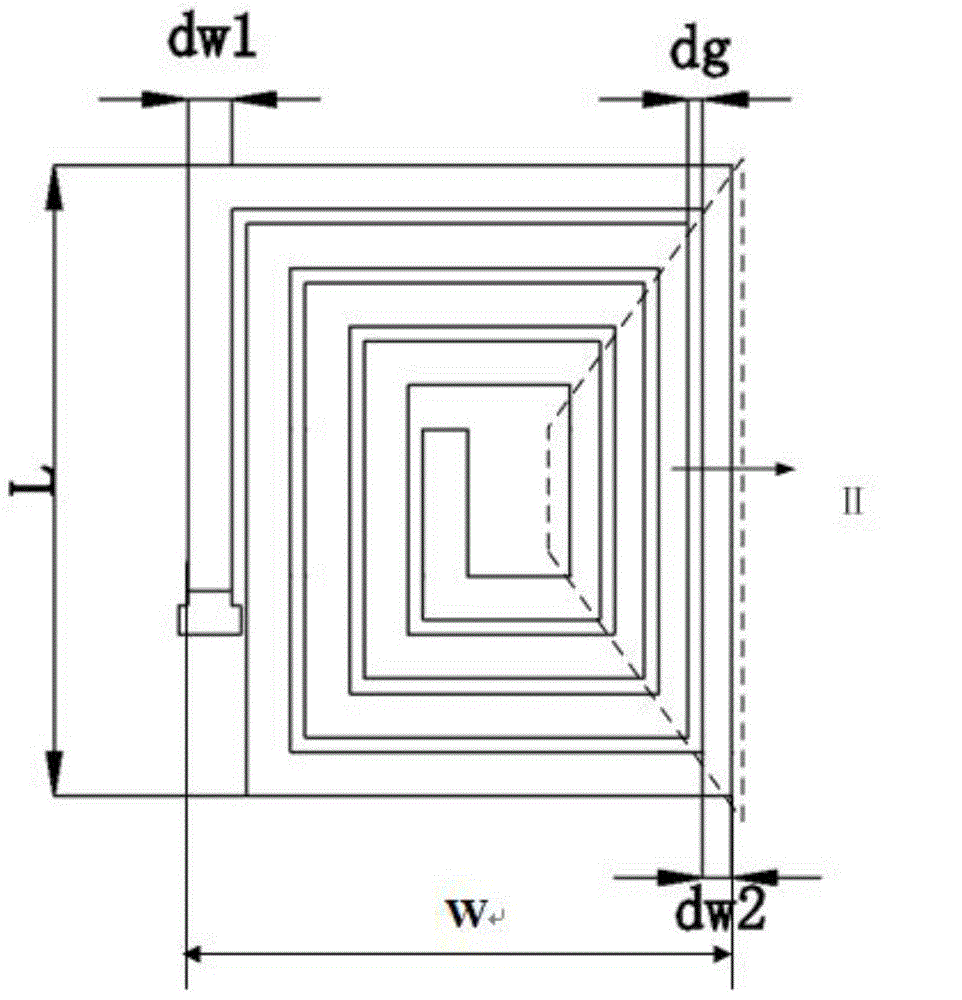
[0043] Step 3: On the first green tape layer obtained in step 2, use silver paste to screen-print the top layer coil, and connect the top layer coil to the top layer coil through the metal through hole in the center of the coil (using silver paste) to form a double layer A coupled set / reset coil layer, wherein the dimensions of the top and bottom coils are: dw1=60 μm, dw2=20 ...


PUM

PropertyMeasurementUnit
Thicknessaaaaaaaaaa
Thicknessaaaaaaaaaa
Thicknessaaaaaaaaaa

Abstract

The invention provides a low-power magnetic resistance sensor based on the LTCC technology and a preparation method therefor, and belongs to the magnetic material and component technology field. The low-power magnetic resistance sensor comprises a substrate and also comprises a bottom layer coil, a first green tape layer, a top layer coil, a second green tape layer and a four-terminal Wheatstone-bridge-type anisotropic magnetic resistance sensing unit layer which are located on the substrate in order. The bottom layer coil and the top layer coil are connected through a metal through hole, current flowing directions in the bottom layer coil and the top layer coil are consistent, and the magnetic field can be enhanced. The magnetic resistance sensor employs setting/resetting coil layers with optimized structures and employs the LTCC technology for preparation, thus a magnetic field meeting application demands is provided based on no addition of any magnetic auxiliary layer, energy consumption caused by setting/resetting operation is lowered, the technology is simple and implementation is easy.

Description

technical field [0001] The invention belongs to the technical field of magnetic materials and components, and in particular relates to a method for preparing a low-power magnetoresistive sensor using LTCC (Low temperature Co-fired Ceramics) technology. Background technique [0002] Anisotropic magnetoresistive sensors use magnetic materials, such as NiFe, CoFe, Co, etc., to present different resistance values ​​under different magnetic fields to detect external magnetic fields; among them, the size R of anisotropic magnetoresistance satisfies: R =R 0 +ΔRcos 2 θ(R 0 : resistance value under zero magnetic field; ΔR: maximum change value of anisotropic magnetoresistance; θ: angle between current direction and magnetization direction of magnetic layer). At present, this type of sensor has been widely used in magnetoresistive encoders, displacement sensors, electronic compasses and other fields. The United States Honeywell company is the main supplier of such sensors. At pre...

Claims


Application Information

Patent Timeline
IPC IPC(8): G01R33/09G01R3/00
Inventor 唐晓莉邹志理苏桦张怀武钟智勇
Owner UNIV OF ELECTRONICS SCI & TECH OF CHINA
Why Eureka
Try Eureka