Umbrella equipment

A kind of equipment and umbrella pole technology, which is applied in the field of multi-functional umbrella equipment, can solve the inconvenience of travelers and other problems, achieve the effects of weight reduction, improvement of personal safety, and reduction of environmental pollution

Inactive Publication Date: 2015-11-04
赖玉春
View PDF6 Cites 2 Cited by
  • Summary
  • Abstract
  • Description
  • Claims
  • Application Information

AI Technical Summary

Problems solved by technology

Due to the large number of items carried

Method used


Image

  • Umbrella equipment
  • Umbrella equipment
  • Umbrella equipment

Examples


Embodiment Construction

[0048] In order to make the above objects, features and advantages of the present invention more comprehensible, the present invention will be further described in detail below in conjunction with the accompanying drawings and specific embodiments.

[0049] Reference herein to "one embodiment" or "an embodiment" refers to a particular feature, structure or characteristic that can be included in at least one implementation of the present invention. "In one embodiment" appearing in different places in this specification does not all refer to the same embodiment, nor is it a separate or selective embodiment that is mutually exclusive with other embodiments.

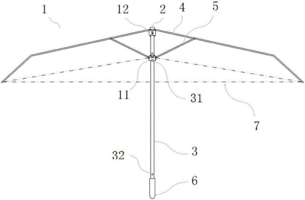
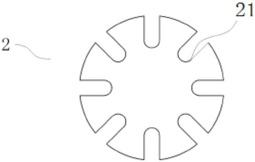
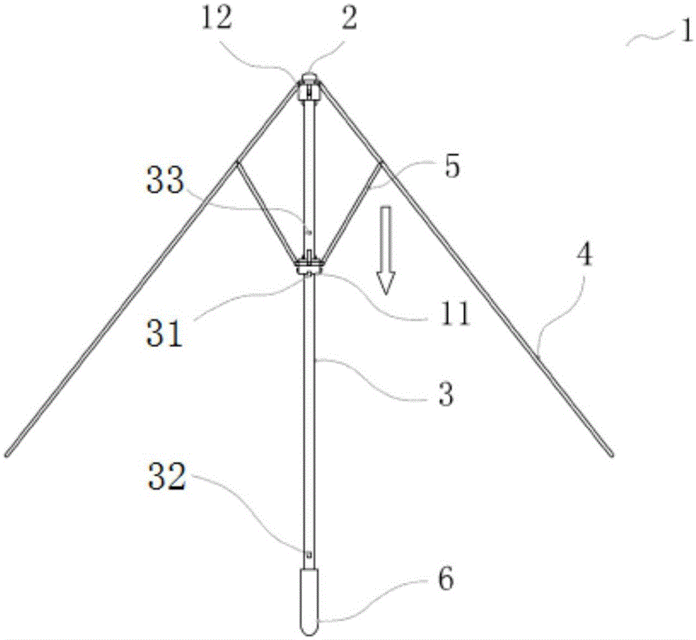
[0050] see figure 1 , which is a schematic view of the expanded state of the umbrella device 1 according to an embodiment of the present invention. like figure 1 As shown, the umbrella device 1 of one embodiment of the present invention includes: an umbrella pole 3, an umbrella cap 2 positioned at the top end of the umbrel...


PUM


Abstract

The invention provides umbrella equipment comprising an umbrella rod, an umbrella cap, a first slide block, a second slide block, an umbrella cloth, ribs and stretchers, wherein the external surface of the umbrella cloth is coated with coating made from a mixture of nano-silver and fluorescent powder. The umbrella rod is made from carbon fiber. The ribs and the stretchers are respectively made from glass fibre. A bracket is movably connected to the umbrella cap. Compared with the prior art, theumbrella equipment is UV resistant and has a function of a selfie rod.

Description

technical field [0001] The invention relates to umbrella equipment, in particular to a multifunctional umbrella equipment. Background technique [0002] At present, common umbrellas are mainly used to block rain or sunlight, but the existing umbrellas have general anti-ultraviolet properties and fewer functions. In particular, when the umbrella is wetted by rain, the entire umbrella cloth is filled with moisture. If it is not placed in a ventilated place to dry in time, bacteria will grow on the umbrella cloth, causing damage to the umbrella cloth, thereby reducing the use of the umbrella. life. [0003] In order to have wind resistance performance in existing umbrellas, the general umbrella handles and umbrella ribs are designed to be heavy, which brings inconvenience to users. [0004] With existing umbrellas, when a user travels at night on a rainy day, the human body does not have obvious night signs to display, and it is difficult to find passing vehicles, which in tu...

Claims


Application Information

Patent Timeline
IPC IPC(8): A45B11/00A45B9/02A45B25/06A45B25/18A45B3/00A45B3/04H04M1/11
Inventor 赖玉春
Owner 赖玉春
Why Eureka
Try Eureka