Slurry separation equipment

A slurry separation and equipment technology, applied in filtration separation, separation methods, and sediment separation by centrifugal force, etc., can solve the problems of affecting the amount of sand discharge, reducing the service life of the device, and wearing blades, so as to achieve a large amount of sand discharge and prevent clogging. , the effect of simple structure

Inactive Publication Date: 2015-11-04
广西容县东润陶瓷原料加工场
View PDF5 Cites 2 Cited by
  • Summary
  • Abstract
  • Description
  • Claims
  • Application Information

AI Technical Summary

Problems solved by technology

Due to the frequent use of the separator, the high-speed rotation of the turbine consumes a lot of energy. The thick slurry obtained after sedimentation and separation will drop, and the suspension will entrain the slurry to rise, which will affect the actual sand discharge. In addition, the high-speed rotating mineral materials and sand will wear the blades and reduce the device. Therefore, there is an urgent need for a slurry separation equipment with low energy consumption, large sand discharge capacity, high work efficiency, good separation effect and long service life.

Method used


Image

  • Slurry separation equipment
  • Slurry separation equipment
  • Slurry separation equipment

Examples


Embodiment Construction

[0025] The present invention will be further described in detail below in conjunction with the accompanying drawings, so that those skilled in the art can implement it with reference to the description.

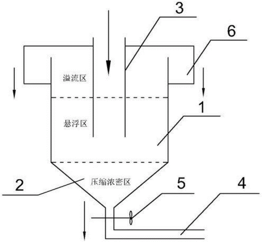
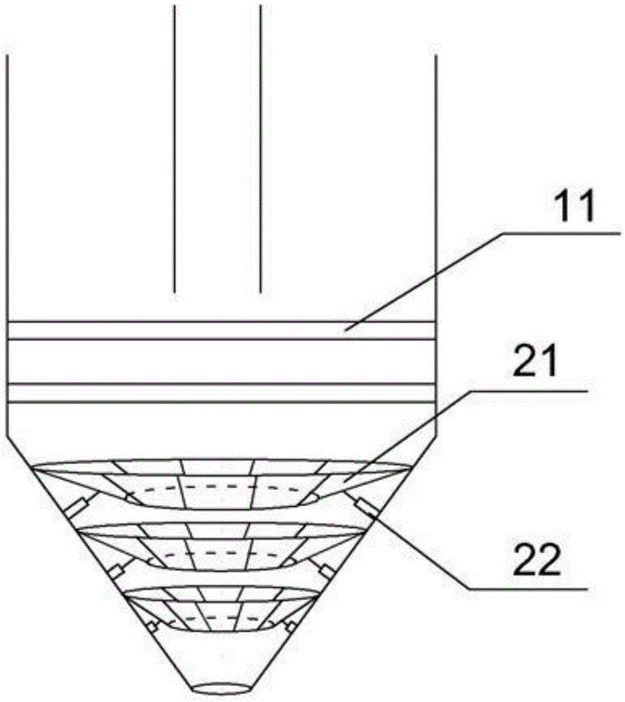
[0026] like Figures 1 to 3 As shown, the present invention provides a slurry separation device, which is integrally formed by a cylindrical first part 1 and a conical second part 2 with the bottom surface facing upwards and the apex facing downwards. The feeding cylinder 3 extends into the first part 1 to introduce the slurry. The interior of the first part 1 and the second part 2 forms a through-space for holding the slurry, and the bottom of the second part 2 is provided with a slurry outlet for leading the separated thick slurry, and communicates with the slurry outlet. The slurry discharge pipe 4 and the valve 5 connecting / disconnecting the slurry discharge pipe 4, wherein, the diameter ratio of the feed cylinder 3 to the slurry discharge pipe 4 is 4-6:1. By designing t...


PUM

PropertyMeasurementUnit
Diameteraaaaaaaaaa
Apertureaaaaaaaaaa
Widthaaaaaaaaaa

Abstract

The invention discloses slurry separation equipment which is integrally formed by a first cylindrical portion and a second conical portion with the upward bottom face and the downward peak. A feeding cylinder stretches into the first portion to guide in slurry. Communicating spaces for containing slurry are formed inside the first portion and the second portion. The bottom of the second portion is provided with a slurry discharge opening, a slurry discharge pipe and a valve, wherein separated thick slurry is guided out through the slurry discharge opening, the slurry discharge pipe is communicated with the slurry discharge opening and the valve is connected or disconnected with the slurry discharge pipe. The diameter ratio of the feeding cylinder to the slurry discharge pipe is 4-6:1. Multilayer vortex can be formed naturally, thick slurry sedimentation is promoted due to progressive separation, and the slurry separation equipment has the advantages of being large in sand discharging amount, good in separation effect, high in working efficiency, long in service life and the like.

Description

technical field [0001] The invention belongs to the technical field of operation separation, and in particular relates to a slurry separation equipment. Background technique [0002] Usually, the slurry separation is composed of a tank and a turbine inside the tank. When working, the slurry inside the tank is separated into different heights according to the specific gravity of the slurry inside the tank under the action of the high-speed rotating turbine inside the tank. Layers, the clear liquid with small specific gravity is discharged from the uppermost layer of the tank body, while the sandstone and mineral materials with large specific gravity located in the lower part of the tank body can be discharged through the slurry discharge port. Due to the frequent use of the separator, the high-speed rotation of the turbine consumes a lot of energy. The thick slurry obtained after sedimentation and separation will drop, and the suspension will entrain the slurry to rise, which...

Claims


Application Information

Patent Timeline
IPC IPC(8): B01D21/02B01D21/26B01D36/04
Inventor 陆汉均黄红棠
Owner 广西容县东润陶瓷原料加工场
Why Eureka
Try Eureka