Portable tool wear measuring instrument and method for predicting remaining service life of tool through measuring instrument

A tool wear and measuring instrument technology, applied in the direction of measuring/indicating equipment, manufacturing tools, metal processing machinery parts, etc., can solve problems such as troublesome installation and debugging, inaccurate judgment, huge software/hardware system, etc., to reduce tool waste, The effect of accurate prediction results and saving clamping time

Inactive Publication Date: 2015-11-04
HARBIN UNIV OF SCI & TECH
View PDF7 Cites 17 Cited by
  • Summary
  • Abstract
  • Description
  • Claims
  • Application Information

AI Technical Summary

Problems solved by technology

[0004] The purpose of the present invention is to solve the problem that the existing tool wear measurement device has a huge software / hardware system, troublesome installation and debugging, is not suitable for use in the actual production process, and the judgment of the service life of the tool is mostly based on manual experience, and the judgment is not accurate. problem, providing a portable tool wear measuring instrument and a method for predicting the remaining service life of a tool using the measuring instrument

Method used


Image

  • Portable tool wear measuring instrument and method for predicting remaining service life of tool through measuring instrument
  • Portable tool wear measuring instrument and method for predicting remaining service life of tool through measuring instrument
  • Portable tool wear measuring instrument and method for predicting remaining service life of tool through measuring instrument

Examples


specific Embodiment approach 1

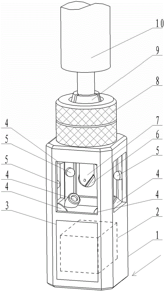
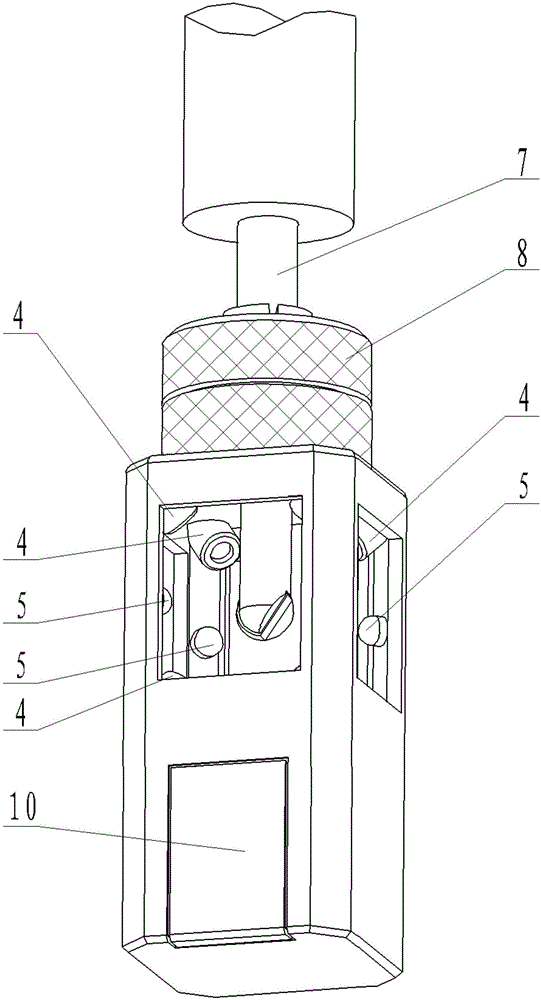
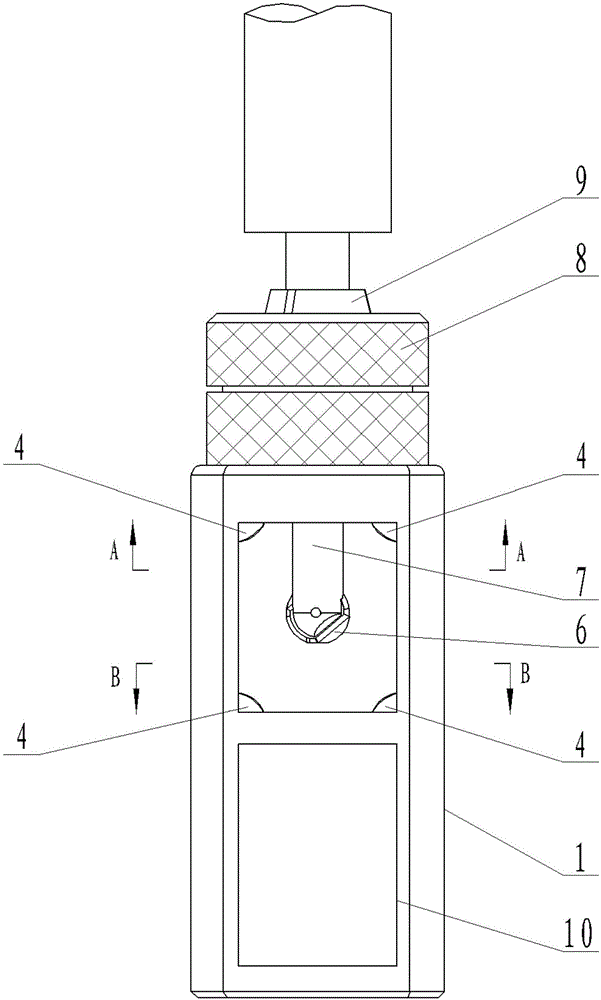
[0029] Specific implementation mode one: combine Figure 1 to Figure 6 Describe this embodiment. The portable tool wear measuring instrument described in this embodiment includes a housing 1, a data processing circuit 2, a display screen 3, one or more cameras 4, one or more light source lamps 5 and a battery 10;

[0030] The top of the housing 1 is provided with an opening, and the opening is used to insert the tool 6 installed on the machine tool into the portable tool wear measuring instrument. A camera 4 and a light source lamp 5 are arranged around the tool 6, and a data processing circuit 2 and the battery 10 are both arranged inside the casing 1, and the display screen 3 is arranged on the outer surface of the casing 1;

[0031] The battery 10 is used to provide working power for the portable tool wear measuring instrument;

[0032] The signal output end of the camera 4 is connected to the image signal input end of the data processing circuit 2 , and the data output en...

specific Embodiment approach 2

[0035] Specific implementation mode two: combination Figure 1 to Figure 3 ,as well as Figure 6 Describe this embodiment. This embodiment is a further limitation of the portable tool wear measuring instrument described in Embodiment 1. In this embodiment, the measuring instrument also includes a locking ring 8 and a tool holder 9. The locking ring 8 It is located outside the top opening of the housing 1, and one end of the locking ring 8 is fixed on the top of the housing 1, and the other end can rotate around the axis of the locking ring 8, and the tool bar clamp 9 is arranged in the central hole of the locking ring 8, The center of the tool bar clamp 9 is also provided with a hole, which is used to place the tool bar 7. When the locking ring 8 rotates, the diameter of the tool bar clamp 9 can be changed.

[0036] like figure 1 As shown, both the locking ring 8 and the tool bar clamp 9 are conventional structures, and the tool bar clamp 9 is divided into the same several p...

specific Embodiment approach 3

[0037] Specific implementation mode three: combination Figure 1 to Figure 3 This embodiment will be described. This embodiment is a further limitation of the portable tool wear measuring instrument described in Embodiment 1. In this embodiment, a window is opened on the side of the casing 1 .

[0038] The window on the side of the housing 1 can be used to observe whether the measuring instrument is installed correctly, and can observe the measurement process in real time. And because the window is opened, external light can enter the casing 1, so the brightness or quantity of the light source lamp 5 can be appropriately reduced, thereby reducing the energy consumption of the measuring instrument.


PUM


Abstract

The invention provides a portable tool wear measuring instrument and a method for predicting the remaining service life of a tool through the measuring instrument and relates to the technology of tool wear measurement. The problems that software/hardware systems of an existing tool wear measuring device is huge, installation and debugging are complex, the service life of a tool is mainly judged by human experience, and judgment is inaccurate are solved. An opening is formed in a shell and used for making the tool extend into the measuring instrument. Cameras and light source lamps are arranged on the periphery of the tool. The brand-new tool is used for cutting a workpiece multiple times according to specific cutting parameters till the tool face abrasion amount reaches the bluntness standard, and cutting time of each time and the tool face abrasion amount are recorded; and the cutting time of each time and the tool face abrasion amount are fitted into a curve through a data processing circuit, and the curve is a service life curve. The abrasion amount of the used tool is measured and compared with the service life curve, so that the service life of the tool is acquired. The portable tool wear measuring instrument is simple in structure, convenient to install and accurate in service life prediction.

Description

technical field [0001] The invention relates to tool wear measurement technology and tool remaining service life prediction technology. Background technique [0002] Most of the existing tool wear measurement devices use various signal sensors, such as acoustic emission sensors, image sensors, etc., and process the signals obtained from the sensors through signal processing equipment, and then send them to the terminal PC. The entire tool wear measurement device is soft / Hardware system is huge, installation and debugging are troublesome, not suitable for use in the actual production process, and before measurement, the blade needs to be removed from the tool holder for measurement, which not only wastes a lot of time, but also easily causes secondary clamping errors. [0003] For the tools that have been worn out, there is no good predictive method for the remaining service life of the tool that can predict the continued use time of the tool. The judgment of tool life in t...

Claims


Application Information

Patent Timeline
Patent Type & Authority Applications(China)
IPC IPC(8): B23Q17/09B23Q17/24
CPCB23Q17/0904B23Q17/0995B23Q17/2404B23Q17/2409
Inventor 刘献礼马晶岳彩旭刘强王冠中
Owner HARBIN UNIV OF SCI & TECH
Why Eureka
Try Eureka