Energy-saving transmission mechanism of ball press machine

A technology of transmission mechanism and ball press, applied in the direction of press, transmission device, gear transmission device, etc., can solve the problems of low ball formation rate, power consumption, short force point, etc., to increase rigidity and stability, product The effect of quality improvement, elimination of bias and skew

Inactive Publication Date: 2015-11-04
郑州市中州型煤机械厂
View PDF11 Cites 1 Cited by
  • Summary
  • Abstract
  • Description
  • Claims
  • Application Information

AI Technical Summary

Problems solved by technology

This traditional transmission method has three serious unreasonable problems as follows: 1. The torque is small, and the power consumption is serious, because the power acts from the center of the roll to the edge of the force point, and the force point is short (compared to the handle of the wrench is short ), the transmission structure is unscientific and unreasonable; 2. The power is transmitted from the driving shaft to the passive shaft. The active bearing is subjected to two kinds of pressure, one is the total transmission force of the equipment, and the other is the separation pressure and tangential force of the active roll ; 3. Since the two rollers of the briquette machine work relatively closely together, this transmission will cause unbalanced transmission and distribution of power generation, and skewing will occur, and unbalanced skewing will cause vibration and micro-shock, which is exactly The shortcoming and key point of the ball pressing machine is that the microseismic shock causes the ball forming rate to be too low, which directly affects the quality of the finished product

Method used


Image

  • Energy-saving transmission mechanism of ball press machine
  • Energy-saving transmission mechanism of ball press machine
  • Energy-saving transmission mechanism of ball press machine

Examples


Embodiment Construction

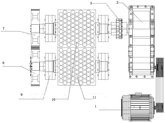
[0018] Such as figure 1 As shown, the traditional transmission mechanism in the field of briquetting machines has worked like this for many years: the motor drives the reducer, and the power is transmitted to the drive shaft of the roll through the coupling on the output shaft of the reducer. The drive shaft drives the main roll to work and drives the drive shaft at the same time Gear, the driving shaft gear drives the driven shaft gear again, the driven gear drives the driven shaft again, and the driven shaft drives the passive roll to work relatively. This traditional transmission method has three serious unreasonable problems as follows: 1. The torque is small, and the power consumption is serious, because the power acts from the center of the roll to the edge of the force point, and the force point is short (compared to the handle of the wrench is short ), the transmission structure is unscientific and unreasonable; 2. The power is transmitted from the driving shaft to the...


PUM


Abstract

The invention relates to an energy-saving transmission mechanism of a ball press machine. The energy-saving transmission mechanism comprises a motor, a speed reducer, a transmission spindle with one end connected with the speed reducer and a transmission main gear fixedly mounted at the other end of the transmission spindle. The transmission spindle is mounted on a conjoined double-shaft bearing seat through transmission bearings, and a driving roller shaft is mounted on the conjoined double-shaft bearing seat through transmission bearings. A ball press machine driving roller is mounted on the driving roller shaft, and a driving roller gear engaged with the transmission main gear is mounted at the end of the ball press machine driving roller. A driven roller shaft is mounted through driven roller shaft bearings and driven roller shaft bearing seats. A ball press machine driven roller is mounted on the driven roller shaft, and a driven roller gear engaged with the driving roller gear is mounted at the end of the driven roller shaft. The driving roller and the driven roller of the ball press machine are matched, and energy conservation is obvious; the acting point of force is long, the load of the speed reducer and the load of the motor are greatly lowered, and the load of the driving roller shaft is reduced; deviation, deflection and slight shock are eliminated, rigidity and stability of the machine are improved, and the product quality is improved.

Description

technical field [0001] The invention belongs to the field of powder briquetting machines, and relates to an energy-saving transmission mechanism of a briquetting machine that can greatly improve product quality. Background technique [0002] The transmission mechanism designed and manufactured for many years in the field of ball briquetting works like this: the motor drives the reducer, and the power is transmitted to the drive shaft of the roll through the coupling on the output shaft of the reducer. The drive shaft drives the main roll to work and drives the drive shaft gear at the same time. , the driving shaft gear drives the driven shaft gear again, the driven gear drives the driven shaft again, and the driven shaft drives the passive roll to work relatively. This traditional transmission method has three serious unreasonable problems as follows: 1. The torque is small, and the power consumption is serious, because the power acts from the center of the roll to the edge ...

Claims


Application Information

Patent Timeline
Patent Type & Authority Applications(China)
IPC IPC(8): B30B15/00B30B11/16F16H1/20F16C35/00
Inventor 武光川
Owner 郑州市中州型煤机械厂
Why Eureka
Try Eureka