A kind of prefabricated T-beam and its method of building continuous beam bridge

A prestressed and prestressed tendon technology, applied in bridge construction, bridges, buildings, etc., can solve problems such as cracks, and achieve the effects of increasing the compressive area, reducing compressive strain, and facilitating transportation and installation.

Inactive Publication Date: 2017-02-15
ZHENGZHOU UNIV
View PDF8 Cites 2 Cited by
  • Summary
  • Abstract
  • Description
  • Claims
  • Application Information

AI Technical Summary

Problems solved by technology

In addition, although the bottom of the negative bending moment area is a compression area, due to the effect of temperature, etc., cracks often appear

Method used


Image

  • A kind of prefabricated T-beam and its method of building continuous beam bridge
  • A kind of prefabricated T-beam and its method of building continuous beam bridge
  • A kind of prefabricated T-beam and its method of building continuous beam bridge

Examples


Embodiment 1

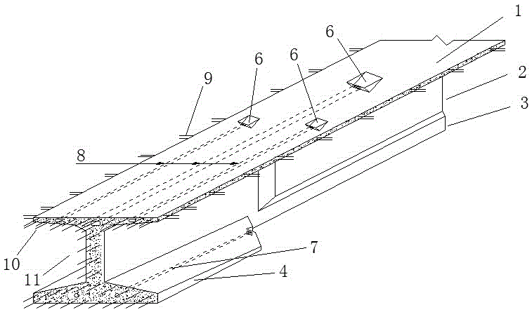
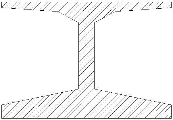
[0016] The first embodiment of the present invention is as figure 1 The prefabricated T-beam shown and the method for constructing continuous beams therefrom. The T-beam is an improved form of a conventional prefabricated T-beam. Within one-eighth of the span at each end, a variable-thickness lower flange 4 is added to the horseshoe 3 under the T-beam web 2 . The thickness of the edge 4 gradually decreases from the end to the mid-span direction. Thus the cross-section of the end is as figure 2 In the I-shape shown, there is a lower flange prestressed tunnel 7 inside the lower flange 4, and the fine-rolled threaded steel bar and the corresponding YGM anchorage are used. There are channels 8 for negative moment tendons in the top plate at the end, flat anchors are used for prestressed tendons, and corresponding tension grooves 6 for negative moment tendons are reserved on the upper surface of the prefabricated beams. On the upper flange, there are protruding steel bars conne...

Embodiment 2

[0028] The second embodiment of the present invention is a modification of the first embodiment, prefabricated T-beams such as Figure 4 shown. There is a longitudinal lower prestressed channel 7 in the lower flange 4, steel strands are used as prestressed tendons, flat anchors are used correspondingly, and corresponding anchoring tooth blocks are provided.

Embodiment 3

[0030] The third embodiment of the present invention is a modification to the first embodiment. The lower flange of the prefabricated T-beam enters the range of the mid-span section in the longitudinal direction. The protruding reinforcement of the edge connection.


PUM


Abstract

The invention relates to a prefabricated T-shaped beam and a method of building a continuous beam bridge by adopting the prefabricated T-shaped beams, and belongs to the field of bridge engineering. The T-shaped beam is an improved form of the conventional prefabricated T-shaped beam, and bottom flanges are additionally arranged at the ends, so that the cross sections of the ends are I-shaped. Longitudinal prestressed ducts are formed in the bottom flanges, and the longitudinal prestressed ducts are also formed in top plates of the ends. The bridge is formed in a manner that the prefabricated T-shaped beams are spliced, simply supported and then connected. Longitudinal prestress is tensioned on the bottom flanges, and negative bending moment prestress is tensioned on the top plates. Certain prestress is exerted on compressed zones at the bottoms, so that cracks under the effects of temperature and the like can be avoided. The compression areas of the bottom flanges are increased, the compressive strain of the compressed zones is decreased under the effect of negative bending moment, correspondingly, the tensile strain at the tops is also decreased and thus the possibility of cracking of the bridge deck can be lowered. As the cross sections of the ends are changed to be I-shaped, transportation and installation are convenient, and the construction of the continuous beam bridge is also convenient. The method of building the continuous beam is convenient to construct, and cracks of the top plates at pier top areas are favorably decreased.

Description

technical field [0001] The invention relates to a prefabricated T-shaped girder and a method for building a continuous girder bridge with it, belonging to the field of bridge engineering. Background technique [0002] With the rapid development of high-grade highways in our country, higher requirements are put forward for the quality of bridges. The current situation is: for small-span high-grade highway bridges, the form of prefabricated reinforced concrete slab girders is mostly used, and for medium-span bridges, prefabricated prestressed concrete T-shaped (box) girders are used. diameter prestressed concrete continuous girder bridge, the current construction method mainly adopts balanced cantilever pouring method or assembly method. However, because the construction of cast-in-situ continuous beams is complicated, labor-intensive and time-consuming, people adopt the method of "simply supported first and then continuous construction", combining the mass prefabrication of ...

Claims


Application Information

Patent Timeline
Patent Type & Authority Patents(China)
IPC IPC(8): E01D19/00E01D21/00
Inventor 魏建东马哲周骥德闫松岭王志洁张丽范兵马一帆
Owner ZHENGZHOU UNIV
Why Eureka
Try Eureka