Formwork with high cantilever structure and construction method thereof

A cantilever and cantilever technology, which is applied to the accessories of the scaffolding, the scaffolding supported by the building structure, the support of the building structure, etc. problems, to avoid welding and dismantling work, save construction resources investment, and achieve the effect of low cost

Active Publication Date: 2015-11-04
HENAN GUOJI CONSTR GRP
View PDF6 Cites 22 Cited by
  • Summary
  • Abstract
  • Description
  • Claims
  • Application Information

AI Technical Summary

Problems solved by technology

[0007] Due to the high position, large span, limited site and large wind load of the traditional cantilevered structure formwork support during the construction of the cantilevered concrete structure, it is difficult to directly use the external support formwork to erect, the con

Method used


Image

  • Formwork with high cantilever structure and construction method thereof
  • Formwork with high cantilever structure and construction method thereof
  • Formwork with high cantilever structure and construction method thereof

Examples


Embodiment 1

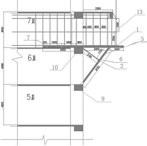
[0040]Embodiment 1: As a very important temporary project in the actual project, the formwork support project directly determines the safety of the project. As a special structural form, the cantilever structure has a disturbance proportional to the fourth power of the span. It can be seen that the influence of the span on the components is extremely significant. The technicians calculated and analyzed the mechanical performance of the formwork support system with a high-altitude cantilever span of 3.7m. The force model of the cantilever and the force of the steel pipe frame of the cantilevered platform are calculated, and the deformation monitoring of the frame is recorded. The following high-altitude cantilever formwork construction method is adopted.

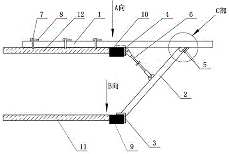
[0041] For the construction method of high-altitude cantilevered formwork, please refer to figure 1 , figure 2 and image 3 , pre-embedded angle steel parts are pre-embedded in the beam on the fifth floor, and the bottom ...

Embodiment 2

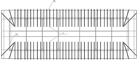
[0099] Example 2: see Figure 2-Figure 8 , the high-altitude suspended formwork can be composed of multiple layers, and each layer is gradually extended, and its construction method is basically the same as that of embodiment 1. The structural relationship is as follows: a diagonally braced I-steel support 5 is welded below the end of the cantilevered I-steel 1 or near the end, and the diagonally braced I-steel support 5 includes an inclined base 52 and two side splints 51 It is matched and docked with the end of the diagonal brace I-beam 2; the bottom angle steel 3 is welded and fixed at the bottom of the diagonal brace I-beam 2, and the bottom angle steel 3 is matched and fixed with the edge of the n-story beam; according to the structural requirements, it is pre-prepared when pouring concrete on the n+1 floor Buried φ22 steel bar U-row clasps with a spacing of 1500. After the concrete pouring has a certain strength, start to arrange 18# cantilevered I-beam 1 with a spacing ...


PUM

PropertyMeasurementUnit
Diameteraaaaaaaaaa

Abstract

The invention discloses a formwork with a high cantilever structure and a construction method thereof. The construction method comprises following steps: utilizing angle iron at bottoms fixed at beam corners in a structure with N layers of beams as support points of a braced steel I-beam; welding and fixing top angle iron in middles of a steel I-beam with a cantilever structure; matching and buckling the top angle iron with corners of beams in n+1 layers; welding and fixing a support of the braced steel I-beam at the end portion of the steel I-beam with the cantilever structure or below by closing to the end portion; and pre-burying at least two round steel pressing rings in a floorslab in the N+1 layer during structural construction. Each round steel pressing ring is firmly welded with the steel I-beam with the cantilever structure or plugged and fixed by a wooden wedge. The high cantilever structure is characterized in that positions of cantilever members are high above the ground. The members with cantilever structures are long in cantilever span lengths and great in deflection produced by structural self-weight. The braced steel I-beam and a welding point position of a horizontal steel I-beam cantilever platform can be determined according to cantilever length. An optimal load-carrying position is within the range spacing from the outside of the span edge of the cantilever members.

Description

technical field [0001] The invention belongs to the technical field of high-altitude suspension formwork construction, and in particular relates to a high-altitude suspension technology of fastener type steel pipe scaffolding. Background technique [0002] As we all know, the application of formwork support technology is an important link in the construction of building structures, and is closely related to the quality of construction projects. Especially the formwork construction of long-span cantilever structures is a construction problem for all construction units. [0003] The floor-to-ceiling scaffold formwork support system used in the traditional formwork support of the cantilever structure has high cost, long working hours, small cantilever span, and no effective guarantee for construction safety. The traditional floor-to-ceiling scaffold formwork construction process is slow and inefficient. Its own rigidity is low, the labor intensity of workers is high, the safety...

Claims


Application Information

Patent Timeline
IPC IPC(8): E04G3/18E04G5/04
Inventor 王叙白高兴文刘友波周静李相伟陈瑞昌倪良才尚培晓阮富荣赵红李朝伟
Owner HENAN GUOJI CONSTR GRP
Why Eureka
Try Eureka