Solar device

A solar device and solar panel technology, which is applied in the field of solar energy sources, can solve the problems that the bracket cannot be adjusted freely, affects the maintenance efficiency, and is easy to be damaged, and achieves the effects of reasonable structure design, improved absorption efficiency, and convenient maintenance.

Inactive Publication Date: 2015-11-04
QINGHAI PANGU NEW ENERGY TECH
View PDF0 Cites 9 Cited by
  • Summary
  • Abstract
  • Description
  • Claims
  • Application Information

AI Technical Summary

Problems solved by technology

[0003] There are at least the following problems in the existing solar installations: 1. Traditionally, the mosquito repellent device adopts phototaxis in metropolises, but there are always areas and places that are not involved in phototaxis. Since the phototaxis mosquito repellent device is open, it is easy to be stained after a long time, which will cause the phototaxis to fail to function normally and lose the effect and efficiency of mosquito repellent; 2. When the solar panel fails, it needs to be removed from the solar panel and placed flat. Maintenance is carried out on the table. However, both sides of the solar panel need to be inspected every time the maintenance is performed. Therefore, the solar panel needs to be turned over. However, some solar panels are relatively large, and it is extremely inconvenient to turn them over. Maintenance efficiency also increases manpower consumption; 3. The existing support cannot be adjusted freely and cannot absorb solar energy to the maximum extent, resulting in low solar energy absorption efficiency

Method used


Image

  • Solar device

Examples


Embodiment Construction

[0017] The present invention will be further described in detail below in conjunction with the accompanying drawings and specific embodiments.

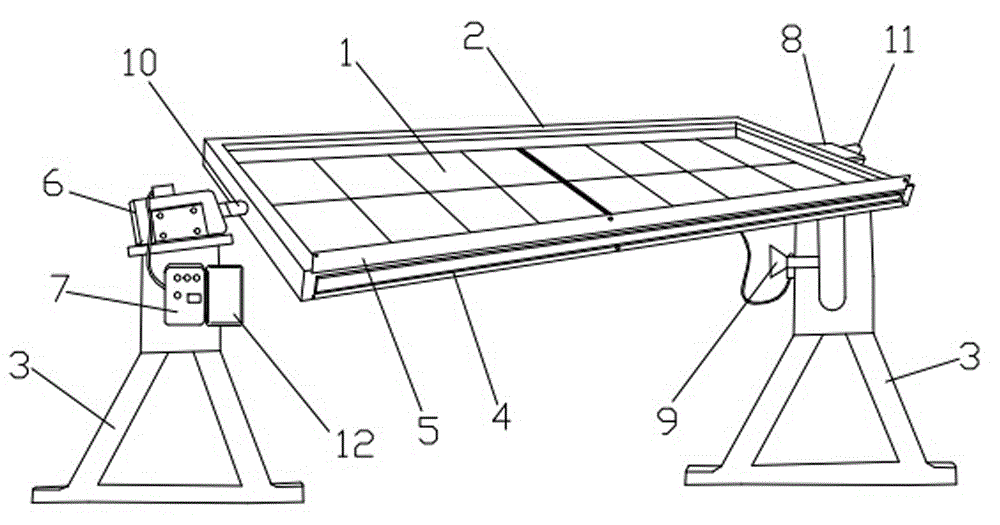
[0018] In this embodiment, refer to figure 1 , its embodiment structure includes more than two solar panels 1, a junction box, an accommodation frame 2 for accommodating the solar panel 1, and a bracket 3 for supporting the accommodation frame 2, and the sides of the solar panel 1 are connected by male and female. Wire terminal connection, so that the two solar panels 1 can be detachably connected into one body, the bottom surface of the solar panel 1 is connected with the connecting wire connected with the junction box, and the junction box is installed at the bottom of the receiving frame 2 and connected with the connecting wire of the junction box .

[0019] The edge of the solar panel 1 has a sliding edge, the front and rear sides of the receiving frame 2 are respectively provided with an opening 4 that can be inserted i...


PUM


Abstract

The invention discloses a solar device and belongs to the technical field of solar energy. The solar device comprises at least two solar panels, a junction box, an accommodating framework used for accommodating the solar panels and a support used for supporting the accommodating framework, wherein a sliding edge is arranged at the border of each solar panel; an opening allowing the solar panels to be inserted therein is formed in each of the front side and the rear side of the accommodating framework; a driving motor which drives the accommodating framework to rotate and a control box which controls the driving motor are arranged at the left upper part of the support; a support seat with a bearing, an induction switch and a mosquito dispeller are arranged at the right upper part of the support; and a left rolling shaft and a right rolling shaft are symmetrically arranged on the left side and the right side of the accommodating framework respectively. The solar device is convenient in integral assembly, maintenance and repair and relatively high in efficiency and saves manpower; the inclined angles of the solar panels can be freely adjusted in the way that the driving motor drives the solar panels on the accommodating framework, so that the solar absorption efficiency is greatly improved; the mosquito dispeller is arranged to effectively avoid the situation that ranges and places, unavailable for a phototatic mosquito dispeller, always exist.

Description

technical field [0001] The invention relates to the technical field of solar energy, in particular to a solar device. Background technique [0002] With the development of the solar energy industry, the scope and field of use of solar energy devices are increasing, and the number of installations is also extremely large. At present, the main component of solar energy devices is the solar panel that converts sunlight into heat or electricity. When in use, the solar panel is fixed by a bracket Install in a sunny place. [0003] There are at least the following problems in the existing solar energy devices: 1. Traditionally, the phototaxis mosquito-repelling device of the metropolis is used, but there are always areas and places that the phototaxis does not involve. Fouling will cause phototaxis to fail to function normally and lose the effect and efficiency of mosquito repellent; 2. When the solar panel breaks down, it needs to be removed from the solar panel and placed ...

Claims


Application Information

Patent Timeline
Patent Type & Authority Applications(China)
IPC IPC(8): F24J2/46F24J2/54F24J2/40H02S20/30A01M29/18
CPCY02E10/47Y02E10/50
Inventor 张倩
Owner QINGHAI PANGU NEW ENERGY TECH
Why Eureka
Try Eureka