Optical axis offset error compensation method and determination apparatus

A technology of optical axis offset and error compensation, applied in the direction of testing optical performance, etc., can solve problems such as affecting personnel operation, optical axis instability, and bad, etc., to ensure consistent alignment, optical axis instability correction, and beneficial effects. significant effect

Inactive Publication Date: 2015-11-04
山东神戎电子股份有限公司
View PDF7 Cites 15 Cited by
  • Summary
  • Abstract
  • Description
  • Claims
  • Application Information

AI Technical Summary

Problems solved by technology

Due to the influence of optical design errors and machining errors, the imaging system has an unstable optical axis offset phenomenon during the zooming process
Due to the error in the consistency of

Method used


Image

  • Optical axis offset error compensation method and determination apparatus
  • Optical axis offset error compensation method and determination apparatus
  • Optical axis offset error compensation method and determination apparatus

Examples


Embodiment Construction

[0013] The present invention will be further described below with reference to the drawings and embodiments.

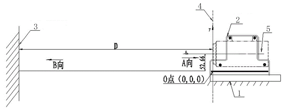
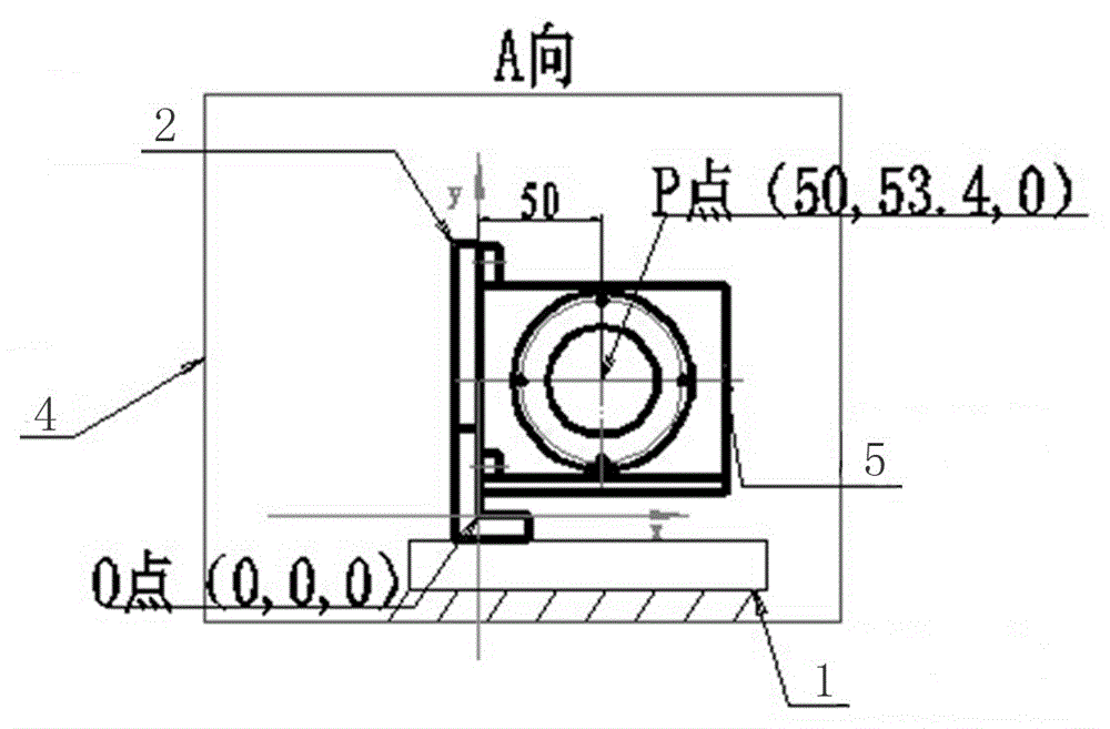
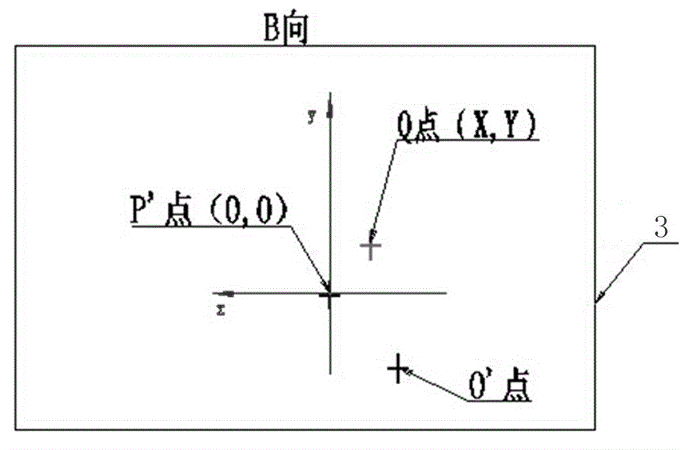
[0014] Such as figure 1 As shown, the structural principle diagram of the optical axis deviation error measuring device of the present invention is given. The installation platform 1 and the fixing device 2 shown constitute a tooling test piece, the installation platform 1 is fixed on the optical test bench, and the fixing device 2 Fixed with the installation platform 1, the optical imaging system 5 is arranged on the fixing device 2. Select the front end surface of the optical imaging system 5 as the reference plane 4, such as figure 2 As shown, gives figure 1 In the A-direction view in, the origin O and the center point P in the optical imaging system are both located in the reference plane 4. The reticle indicating board 3 shown is located at the front end of the reference plane 4, preferably at a distance of 10-30 m, and the reticle indicating board 3 is parallel to...


PUM


Abstract

The optical axis offset error compensation method of the present invention comprises the following steps: first, in the process of an optical imaging system changes from the longest focal length to the shortest focal length or from the shortest focal length to the longest focal length, several zooming positions are uniformly selected and the offset amount of a lower optical axis in the corresponding position is marked; then, the zooming position and the offset amount are stored as a compensation reference value; when using the compensation reference value, find the offset amount that should be compensated from the compensation reference value based on the current focal length value of the optical imaging system to compensate the optical imaging system. The determination apparatus of the present invention comprises an installation platform, a fixing device and a dividing indicator panel. According to the optical axis offset error compensation method and the determination apparatus, a holder servo-actuated system finds the corresponding offset amount from the compensation reference value based on the current focal length value to compensate the optical imaging system and to correct the instability of the optical axis of the optical imaging system. In this way, the center of the field of view is kept aligned with the object always, and the beneficial effect is substantial.

Description

Technical field [0001] The present invention relates to an optical axis offset error compensation method and measuring device, and more specifically, to a method that firstly measures the optical axis offset during the zooming process of an optical imaging system, and then uses the pre-measured offset during use. Optical axis offset error compensation method and measuring device that compensate for Background technique [0002] Optical imaging systems have been widely used in all walks of life in society. Due to the influence of optical design errors and mechanical processing errors, the imaging system has an unstable deviation of the optical axis during the zooming process. Due to the error in the consistency of the optical axis, the accurate alignment of the target cannot be achieved, which affects the next step of the operation of the personnel, and even misleads the operator, resulting in adverse consequences. Summary of the invention [0003] In order to overcome the shortc...

Claims


Application Information

Patent Timeline
IPC IPC(8): G01M11/02
Inventor 丁鉴彬高倩陶小凯张帆
Owner 山东神戎电子股份有限公司
Why Eureka
Try Eureka