A self-grounded antenna arrangement

A technique for grounding antennas, central parts, applied in the direction of antennas, resonant antennas, antenna grounding devices, etc.

Active Publication Date: 2015-11-04
GAPWAVES
View PDF5 Cites 3 Cited by
  • Summary
  • Abstract
  • Description
  • Claims
  • Application Information

AI Technical Summary

Problems solved by technology

Therefore, this mutual coupling should be low, but any compact multiport antenna with low mutual coupling between ports is not known

Method used


Image

  • A self-grounded antenna arrangement
  • A self-grounded antenna arrangement
  • A self-grounded antenna arrangement

Examples


Embodiment Construction

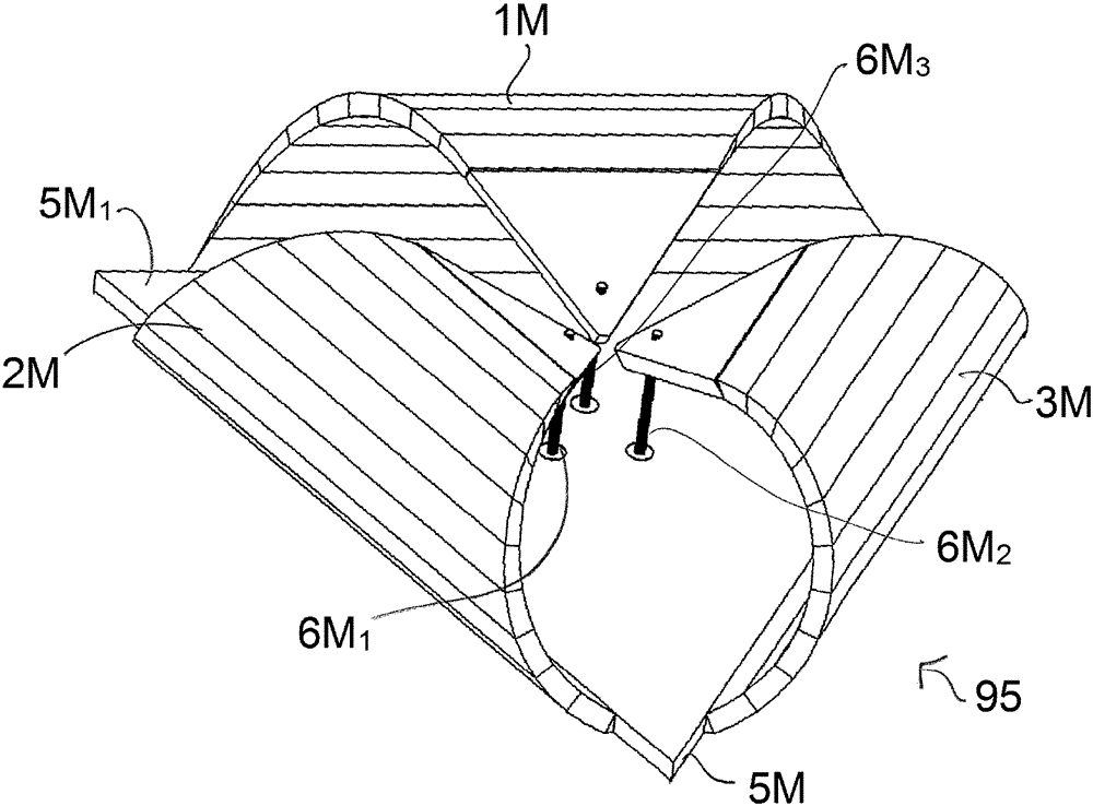
[0041] figure 1 A bow tie antenna structure 10 of a first embodiment of the invention is shown. The bowtie antenna structure 10 comprises four arms 1 , 2 , 3 , 4 arranged such that two arms 1 , 2 are on the first side 5 of the central part 5 1 (Denoted here as upper sides, just for definition) Curved back towards each other. In this embodiment they are bent such that the ends of the arms point towards said upper side 5 1 center of. These ends connect to connector pin 6 1 、6 2 , which via the separated opening 7 1 、7 2 Connections are made to conductors 21 , 22 (dotted lines), which are located on opposite (lower) sides of the central part 5 and point towards opposite side edges of the central part 5 .

[0042] In an advantageous embodiment, the central part comprises a circuit board with microstrip conductors. On the other, second side of the central part 5 the conductors 23, 24 of the arms 3, 4 bent backward towards the center, are located on the first side 5 of the c...


PUM


Abstract

The present invention relates to a self-grounded antenna arrangement (10) comprising a base or central portion (5) arranged in a first plane and a number of arm sections (1,2,3,4) associated with said central portion (5), which taper towards a respective end tip. It comprises an electric conducting material, each arm section being adapted to form a transition from the central portion and being bent backwards towards the central portion by more than 180° so that its end tip approaches a first side of the central portion, at an opening therein. The end tip is connected to feeding means for feeding via an arm section specific port, one specific port ( 111, 112,113; 114;) for each arm section. Each arm section (1,2,3,4) comprises a mixed functionality of a curved monopole antenna and a loop antenna, and the antenna arrangement provides substantially uncoupled ports with far field functions that are almost orthogonal in polarization, direction or shape. The invention is in particular intended for use in MIMO antenna systems for statistical multipath environments.

Description

technical field [0001] The invention relates to an antenna structure having the features of the first part of claim 1 . [0002] The invention also relates to a method for producing an antenna structure having the features of the first part of claim 29 . Background technique [0003] There is an increasing demand for wideband antennas in wireless communication devices in order to allow communication in several frequency bands and for different systems. An ultra-wideband (UWB) signal is generally defined as a signal with a large relative bandwidth (bandwidth divided by the carrier frequency) or a large absolute bandwidth. The term UWB is used in particular for the frequency band 3.2-10.6 GHz, but also for other and wider frequency bands. [0004] The use of wideband signals is associated with many positive aspects and advantages, such as described in "History and applications of UWB" by M.Z. Win et al., see Proceedings of the IEEE, vol. 97, No. 2, p.198- 204, February 2009...

Claims


Application Information

Patent Timeline
Patent Type & Authority Applications(China)
IPC IPC(8): H01Q1/36H01Q9/26
CPCH01Q21/24H01Q5/25H01Q9/28H01Q1/48H01Q9/26H01Q9/40H01Q9/43H01Q21/0087
Inventor 杨健阿里·阿尔-拉维马格努斯·弗兰岑查理·欧利厄斯艾哈迈德·A·基什克
Owner GAPWAVES
Why Eureka
Try Eureka