Inductive load driver slew rate controller

A conversion rate and rate control technology, applied in electronic switches, electrical components, pulse technology, etc., can solve problems such as low system efficiency

Inactive Publication Date: 2015-11-04
MICROCHIP TECH INC
View PDF3 Cites 4 Cited by
  • Summary
  • Abstract
  • Description
  • Claims
  • Application Information

AI Technical Summary

Problems solved by technology

Any such delays accumulate over time and cause unaccep

Method used


Image

  • Inductive load driver slew rate controller
  • Inductive load driver slew rate controller
  • Inductive load driver slew rate controller

Examples


Embodiment Construction

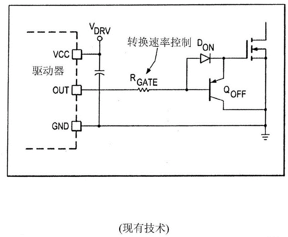
[0023] figure 1 Description Use a resistor R in series between the load driver circuit and the load switch GATE conventional slew rate control of the load driver circuit. Using a series resistor in this way moderates the voltage V across the load DS The rate of change, which reduces the amount of EMI and mitigates the kickback produced by rapid changes in the output voltage used to drive current loads. Using a series resistor to moderate the slew rate of the load switching does not provide sufficient control over the rate of change of the voltage across the load because the behavior of the resistor varies depending on the operating temperature of the system and because the resistor cannot account for the load switching rate. The margin variation in the switch (which can be significant when using transistor load switches such as MOSFETs) or the actual current drawn by the load. Furthermore, conventional resistor-based slew rate control is an open-loop solution that must be ...


PUM


Abstract

A circuit and method for digital controlling the slew rate of load voltage are provided. The circuit is comprised of a digital slew-rate control unit that utilizes a feedback signal to generate control signals where the feedback signal indicates the observed rate of voltage change on the load. The circuit is further comprised of a load driver circuit that is operated by the control signals and provides a slew-rate controlled output voltage used to operate a load switch, where the load switch provides power to the load. The circuit is configured to operate the load switch using a slew-rate controlling driver, depending on the state of the load switch transition, and a non-controlling driver.

Description

[0001] Cross References to Related Applications [0002] This application claims the benefit of US Provisional Application No. 61 / 775,523, filed March 9, 2013, which is incorporated herein in its entirety. technical field [0003] The present invention relates to a slew rate controller for a load driver circuit; in particular, the present invention relates to a driver circuit for providing power to an inductive load, such as a motor or a switched mode power supply (SMPS). Background technique [0004] Various modern electronic devices utilize load switches to control the delivery of power to a load that draws current from an available power supply such as a motor or SMPS. A load driver circuit is used to exert control over the load switch. In addition to determining when the load switch provides power to the load, the load driver circuit can also control the rate of change of the load's properties. The rate of change of these properties is often referred to as the slew ra...

Claims


Application Information

Patent Timeline
IPC IPC(8): H03K17/16
CPCH03K17/6871H03K17/166H03K17/167H03K2217/0063H03K2217/0072H03K5/04
Inventor 巴尔特·德耶特尼古拉斯·富雷尔
Owner MICROCHIP TECH INC
Why Eureka
Try Eureka