
Forcing device of cervical vertebra tractor

A technology of cervical traction device and booster device, which is applied in the field of cervical traction devices, can solve problems such as increased labor intensity of nursing staff, poor force precision, and inability to automatically control and record treatment parameters, and achieve treatment parameter adjustment and storage records Convenience, improve treatment comfort, improve the effect of rehabilitation

Inactive Publication Date: 2015-11-11
HENAN UNIV OF SCI & TECH
View PDF8 Cites 5 Cited by
  • Summary
  • Abstract
  • Description
  • Claims
  • Application Information

AI Technical Summary

Problems solved by technology

[0003] At present, a large number of mechanical bedside tractors are used in hospitals. Although this tractor has the advantages of simple structure, low price, and small space occupation, it also has the following disadvantages: ①The change of the traction force is manually performed by medical staff. It is achieved by increasing or decreasing the weight of the weight, so the accuracy of the force is poor; ②The traction force is applied or removed suddenly, which will cause discomfort in the cervical spine of the patient at the beginning and end of the treatment; ③The weight itself is relatively heavy and requires a large The operating force increases the labor intensity of the nursing staff; ④ The treatment parameters cannot be automatically controlled and recorded, and accurate treatment data cannot be provided to the clinic

Method used


Image

  • Forcing device of cervical vertebra tractor
  • Forcing device of cervical vertebra tractor
  • Forcing device of cervical vertebra tractor

Examples


Embodiment Construction

[0019] The present invention will be further described in detail below in conjunction with the accompanying drawings and specific embodiments.

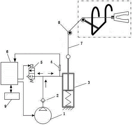
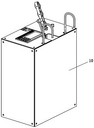
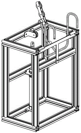
[0020] As shown in the figure, a booster device of a cervical traction device is connected to one end of the tractor. The booster device includes an air compressor 1 and a cylinder 3, and the air compressor 1 is connected to the cylinder through an air intake pipeline. 3, a check valve 2 is provided at the end of the intake pipeline close to the air compressor 1, and an electromagnetic reversing valve 5 is also provided on the intake pipeline between the check valve 2 and the intake end of the cylinder 3. And the pressure sensor 4 used to detect the air pressure in the intake pipeline, the output end of the pressure sensor 4 is connected to the controller 6, and the detected air pressure signal is fed back to the controller 6. The controller 6 is provided with two control loops, one The control loop is connected to the electromagnetic...


PUM


Abstract

Provided is a forcing device of a cervical vertebra tractor. The forcing device is connected with one end of the tractor. The forcing device comprises an air compressor and a cylinder. The air compressor is connected with an air inlet end of the cylinder through an air inlet pipeline. A one-way valve is arranged at the end, close to the air compressor, on the air inlet pipeline. The portion, located between the one-way valve and the air inlet end of the cylinder, of the air inlet pipeline is provided with an electromagnetic reversing valve and a pressure sensor used for detecting air pressure in the air inlet pipeline. The output end of the pressure sensor is connected with a controller and feeds back a detected pressure signal to the controller. The controller is provided with two control circuits. One control circuit is connected with the electromagnetic reversing valve, and the other control circuit is connected with the air compressor. A piston rod of the cylinder is connected with a traction line. The traction line is connected with the tractor through a guide wheel. Various treatment modes such as continuous traction and intermittent traction are selected according to specific conditions of patients. The change process of traction force can be freely designed. The forcing device has the auxiliary functions of traction force automatic compensation, automatic timing, excessive traction force or out-of-control protection and the like.

Description

technical field [0001] The invention relates to a cervical vertebra tractor, in particular to a force applying device of the cervical vertebra tractor. Background technique [0002] Cervical traction, as one of the main non-surgical treatments for cervical diseases, has a long history and is often used as the first choice or main treatment because of its definite curative effect. Traction therapy is widely used for its simplicity, safety, painlessness and effectiveness. [0003] At present, a large number of mechanical bedside tractors are used in hospitals. Although this tractor has the advantages of simple structure, low price, and small space occupation, it also has the following disadvantages: ①The change of the traction force is manually performed by medical staff. It is achieved by increasing or decreasing the weight of the weight, so the accuracy of the force is poor; ②The traction force is applied or removed suddenly, which will cause discomfort in the cervical spin...

Claims


Application Information

Patent Timeline
IPC IPC(8): A61F5/045
Inventor 韩建海郭冰菁李向攀吴鹏李鹏杰练书君李文肖
Owner HENAN UNIV OF SCI & TECH
Learn More