
A condensation recovery device

A technology of condensation recovery and condensation chamber, which is applied in the direction of steam condensation, separation of dispersed particles, chemical instruments and methods, etc., and can solve problems such as inability to obtain high-standard raw materials

Active Publication Date: 2018-03-02
ANHUI XOANONS CHEM
View PDF3 Cites 0 Cited by
  • Summary
  • Abstract
  • Description
  • Claims
  • Application Information

AI Technical Summary

Problems solved by technology

[0003] The technical problem to be solved by the present invention is to provide a condensation recovery device to solve the problem that the traditional refining method of chemical raw materials cannot obtain high-standard raw materials

Method used


Image

  • A condensation recovery device
  • A condensation recovery device
  • A condensation recovery device

Examples

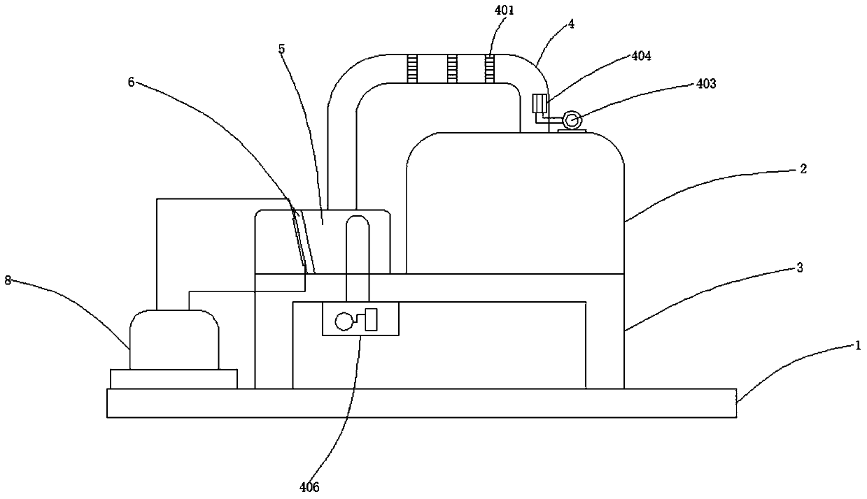
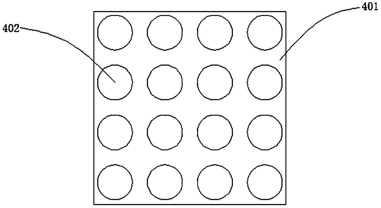
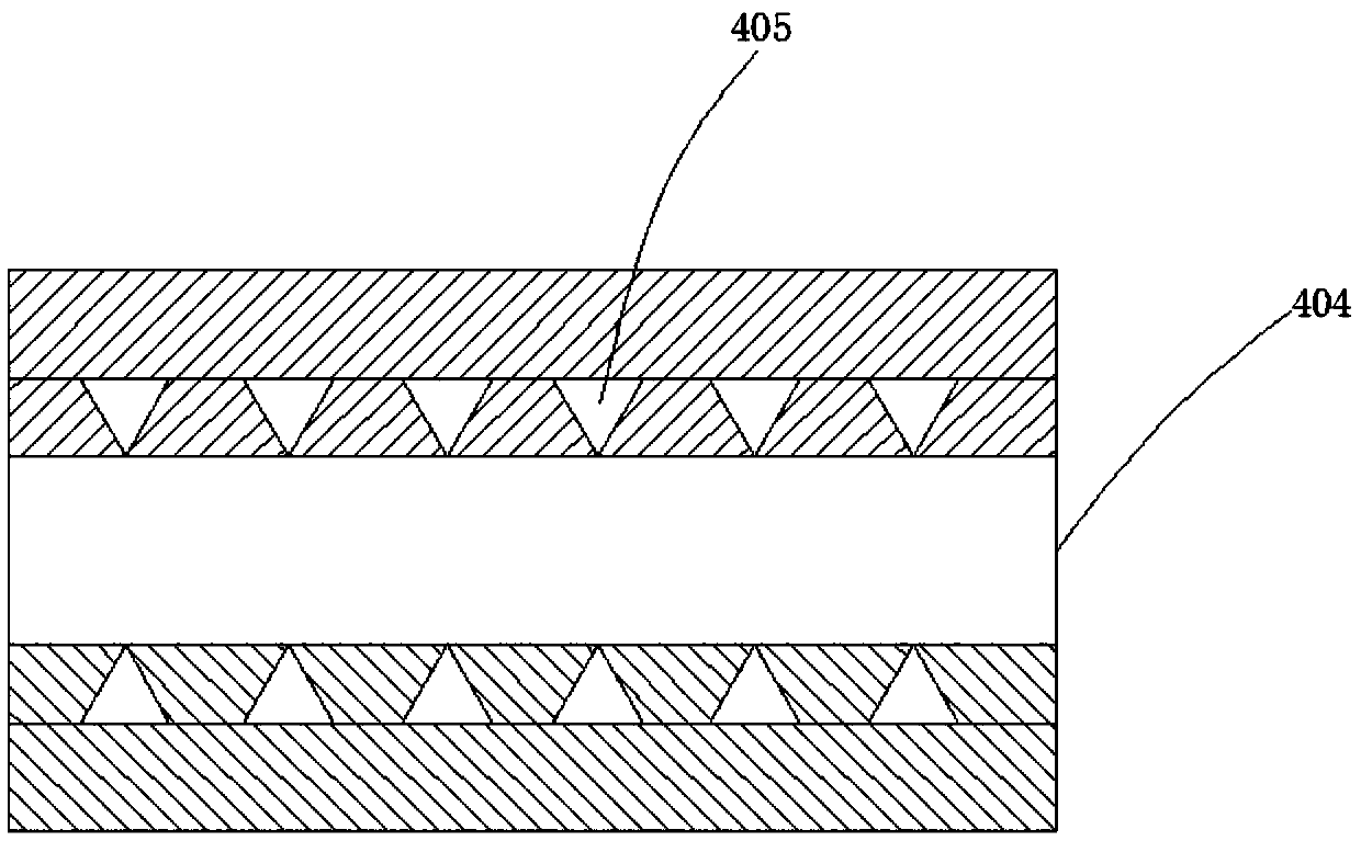

Embodiment Construction

[0024] In the following, numerous specific details are set forth in order to provide a thorough understanding of the concepts underlying the described embodiments. It will be apparent, however, to one skilled in the art that the described embodiments may be practiced without some or all of these specific details. In other instances, well known processing steps have not been described in detail.

[0025] Such as figure 1 , figure 2 , image 3 , Figure 4 As shown, it includes a working table 1, a reaction kettle 2, a frame 3, a collection pipe 4, a condensation chamber 5, a crystallization plate 6, a condensation water channel 7, a cooling water tower 8, a pre-cooling plate 401, a ventilation hole 402, a blower 403, and liquid nitrogen Placement pipe 404, release hole 405, suction fan 406, frame 3 is located at the top of worktable 1, collection pipe 4 is located at the top of reaction kettle 2, the two are connected by threads, condensation chamber 5 is located on the lef...


PUM


Abstract

The invention discloses a condensation recovery device, which comprises a working table, a reaction kettle, a frame, a collection pipe, a condensation chamber, a crystallization plate, a condensation water channel, and a cooling water tower. The frame is located on the top of the working table, and the collecting The pipeline is located on the top of the reactor, and the two are connected by threads. The condensation chamber is located on the left side of the top of the frame, and the two are connected by threads. The crystallization plate is located in the middle of the condensation chamber, and it is 10°-15° to the bottom of the condensation chamber. The two are connected by welding, the condensation water channel is located on the back of the crystallization plate, and the two are connected by buckles, and the cooling water tower is located on the left side of the top of the worktable. Collection is carried out to realize the effective recovery of poisonous gas and avoid pollution leakage.

Description

technical field [0001] The invention relates to a recovery device, in particular to a condensation recovery device. Background technique [0002] When making chemical materials, various raw materials are mixed and reacted in the reactor to obtain chemical products, but a large amount of poisonous gas will be generated during the reaction process. Traditional sealing methods can only conservatively suppress gas leakage, but cannot fundamentally eliminate leakage. Thereby cause great potential safety hazard to operating personnel and environment, in view of above-mentioned defective, be necessary to design a kind of condensation recovery device really. Contents of the invention [0003] The technical problem to be solved by the present invention is to provide a condensation recovery device to solve the problem that high-standard raw materials cannot be obtained by traditional refining methods of chemical raw materials. [0004] In order to solve the above-mentioned technica...

Claims


Application Information

Patent Timeline
Patent Type & Authority Patents(China)
IPC IPC(8): B01D53/00B01D5/00
Inventor 陈永康
Owner ANHUI XOANONS CHEM
Learn More