
Electromachining method for preventing electrochemical dispersion corrosion

A stray corrosion and electrochemical technology, applied in electric machining equipment, electrochemical machining equipment, metal machining equipment, etc., can solve the problems of stray corrosion in the non-machined area of ​​the bottom end face of the electrode, reduction of workpiece machining accuracy and surface quality, etc. Achieve the effect of reducing stray corrosion, improving surface quality and forming accuracy, and reducing movement

Inactive Publication Date: 2015-11-11
TSINGHUA UNIV
View PDF6 Cites 7 Cited by
  • Summary
  • Abstract
  • Description
  • Claims
  • Application Information

AI Technical Summary

Problems solved by technology

The stray corrosion on the end face of the electrode mainly occurs at the beginning of the electrolytic machining process, because the electrode / workpiece gap is much larger than the balance gap. When the electrode moves to the balance gap, the bottom end of the electrode faces the non-processing area of ​​the workpiece surface. The stray corrosion is serious , resulting in a significant reduction in the machining accuracy and surface quality of the workpiece. Therefore, the stray corrosion of the electrode end face has always been the bottleneck for the improvement of the electrolytic machining accuracy and the surface quality of the workpiece.

Method used


Image

  • Electromachining method for preventing electrochemical dispersion corrosion
  • Electromachining method for preventing electrochemical dispersion corrosion
  • Electromachining method for preventing electrochemical dispersion corrosion

Examples


Embodiment Construction

[0011] The present invention will be described in detail below in conjunction with the accompanying drawings and embodiments.

[0012] The method for preventing electrochemical stray corrosion in electrical machining provided by the invention comprises the following steps:

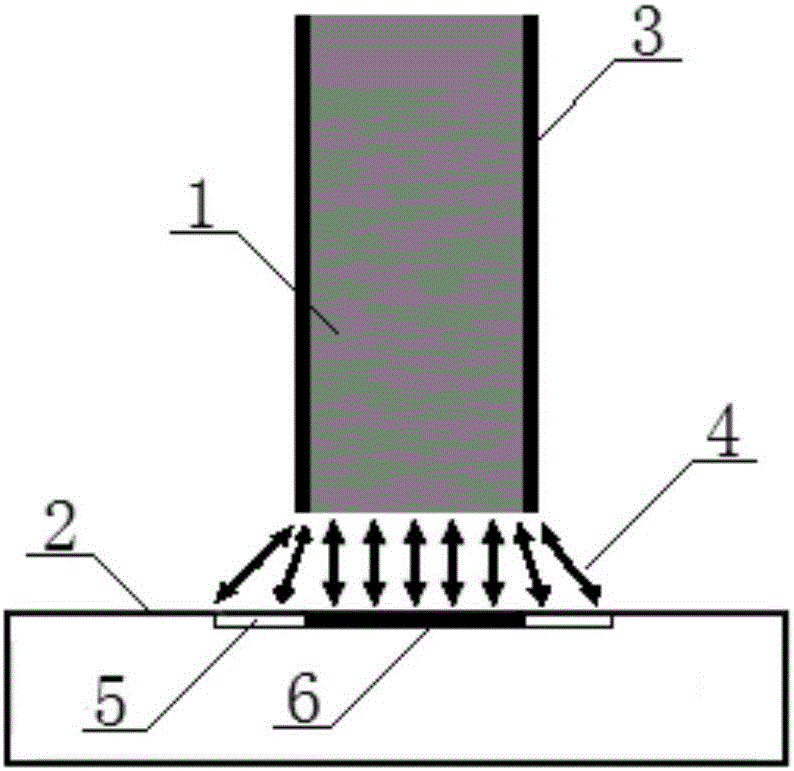
[0013] 1) if figure 1 As shown, the side of the tool electrode 1 is provided with a circle of insulating film layer 3, the tool electrode 1 is fixed on the main shaft of the existing machine tool, the workpiece 2 to be processed is fixed in the electrolytic cell of the machine tool table, the tool electrode 1 and the workpiece 2 Connect the negative pole and the positive pole of the power supply respectively to form a loop. A current sensor for real-time collection of the loop current is set on the loop, and the current sensor sends the collected current value to the existing controller in real time;

[0014] 2) The tool electrode 1 reaches the initial position (starting position) of the machining under t...


PUM


Abstract

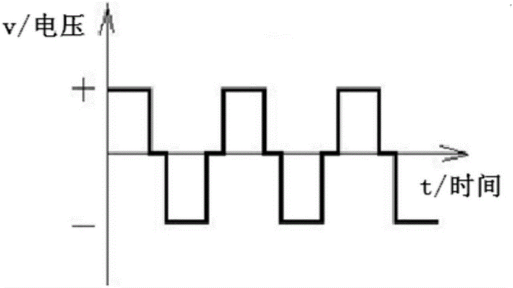
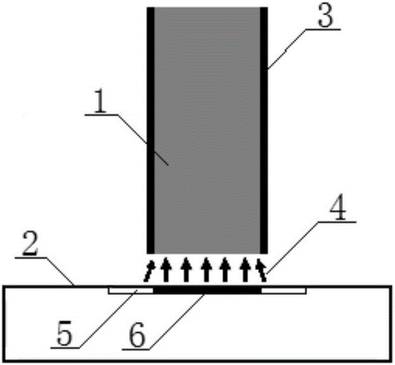
The invention relates to an electromachining method for preventing electrochemical dispersion corrosion. The method includes the following steps that firstly, a tool electrode is fixed to a machine tool spindle, a workpiece is fixed into an electrolytic tank of a machine tool workbench, the tool electrode and the workpiece are connected with the negative electrode and the positive electrode of a power source respectively for forming a circuit, a current sensor is arranged in the circuit, and collected current values are sent to a controller by the current sensor in real time; secondly, the tool electrode reaches an initial position; thirdly, the tool electrode continues to move to the workpiece, and switch of the power source is controlled by the controller so that an alternating-current auxiliary power source with the positive electrode and the negative electrode symmetrical can be applied between the tool electrode and the workpiece; fourthly, the pulse width and the frequency of the alternating-current auxiliary power source are adjusted so that ions and electrons between the tool electrode and the workpiece can move back and forth along the initial position; fifthly, as the tool electrode gets close to the workpiece gradually, the current value is gradually increased, and when the current value does not change, the gap between the tool electrode and the workpiece is a balance gap; and sixthly, the controller controls the power source to be switched to an electrolysis machining main power source so that the workpiece can be machined.

Description

technical field [0001] The invention relates to the technical field of precision electrolytic machining, in particular to a method for preventing electrochemical stray corrosion for electrical machining. Background technique [0002] In the process of electrolytic machining, the anode material of the workpiece is removed in the form of ions, and the size of metal ions is very small. This material removal method makes electrolytic machining have the ability of micromachining. In addition, electrolytic machining also has the advantages of no remelting metamorphic layer on the machined surface and no loss of tool electrodes, so it is widely used in micro-hole machining of metal materials in the fields of micro-electromechanical systems, automobiles, aerospace, and medical treatment. [0003] Since the electric field cannot be completely confined to the expected area during electrolytic machining, the non-machined area on the workpiece is machined and the machined area is re-pro...

Claims


Application Information

Patent Timeline
Patent Type & Authority Applications(China)
IPC IPC(8): B23H3/00B23H11/00
Inventor 韩福柱陈伟
Owner TSINGHUA UNIV
Learn More