
Vacuum sucker

A technology of vacuum suction cups and suction cups, which is applied in the field of mechanical equipment, can solve problems that affect production efficiency and machine utilization, large investment cannot be effectively returned, and fast and efficient clamping cannot be achieved, so as to improve processing efficiency and facilitate operation , adsorption and stable effect

Inactive Publication Date: 2015-11-11
XIANGSHAN WEIHUI MAGNET
View PDF9 Cites 3 Cited by
  • Summary
  • Abstract
  • Description
  • Claims
  • Application Information

AI Technical Summary

Problems solved by technology

Therefore, the interval between workpiece clamping in the workshop will be shorter and shorter, that is to say, the frequency of workpiece replacement will be higher and higher. However, the conventional manual clamping method is still used at present, and the required clamping time will be greatly increased. Seriously It affects production efficiency and machine utilization rate, prolongs the delivery cycle, and cannot effectively return a large investment; in addition, it is particularly difficult to clamp when processing workpieces, especially parts with small dimensions
[0003] The existing technology cannot achieve fast and efficient clamping, so it is currently necessary to design a vacuum chuck that can quickly achieve clamping

Method used


Image

  • Vacuum sucker
  • Vacuum sucker

Examples


Embodiment Construction

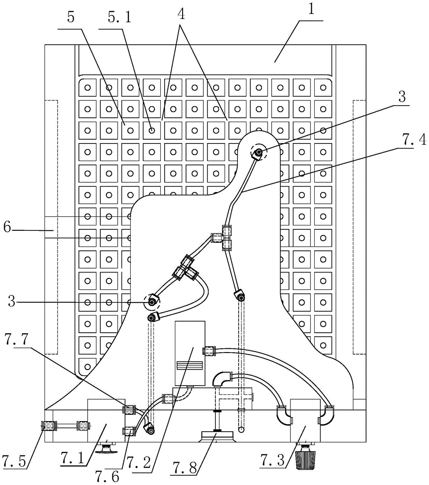
[0018] figure 1 The plan view of the present invention in , wherein the part separated by the curve is a schematic diagram of the back, which is a perspective drawing for easy understanding.

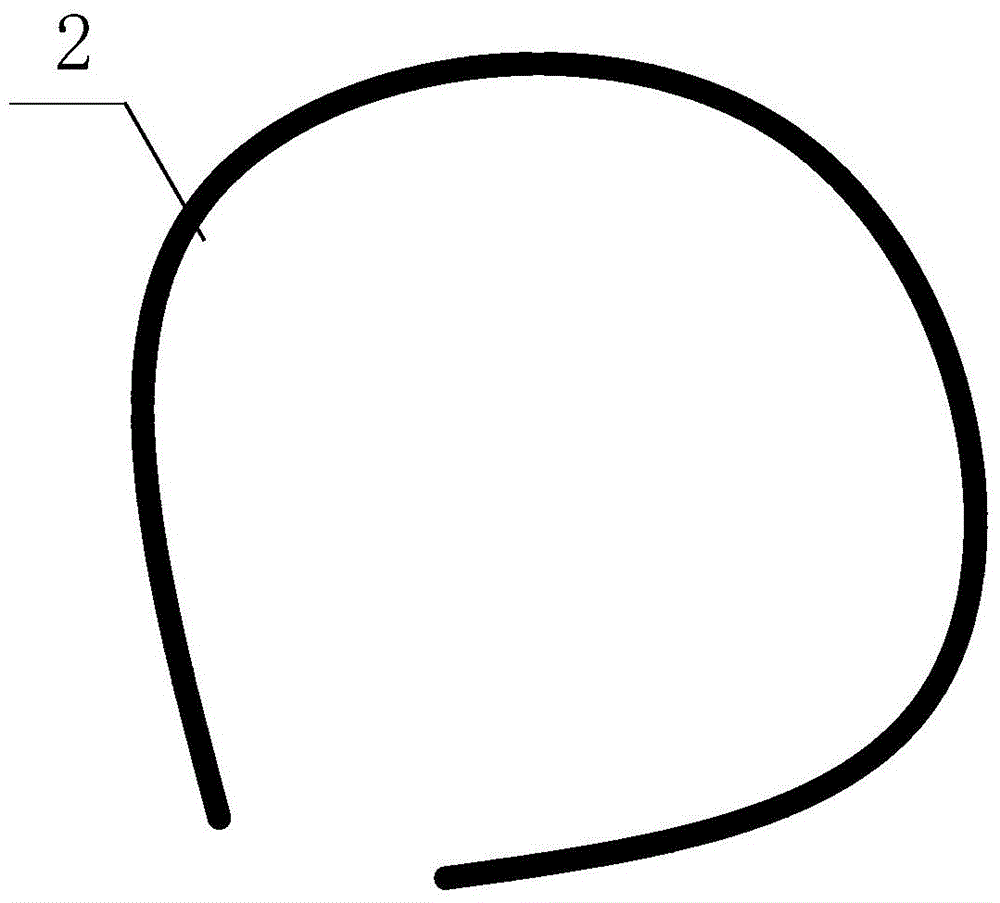
[0019] refer to figure 1 , figure 2 A vacuum suction cup is shown, including a suction cup body 1, an elastic seal 2 and a negative pressure forming component. A closed ring is formed between the front of the suction cup body 1 and the elastic seal 2, and the suction cup body 1 has several negative pressures in the closed ring. Hole 3, the negative pressure hole 3 communicates with the negative pressure forming component.

[0020] The front surface of the suction cup body 1 is arranged with a plurality of criss-cross grooves 4, and several closed groove rings can be formed between the grooves 4, and the elastic sealing member 2 is assembled in the closed groove rings.

[0021] The plurality of grooves 4 divide the front of the suction cup body 1 into a plurality of component blocks 5...


PUM


Abstract

The invention relates to a vacuum sucker which comprises a sucker body, an elastic sealing part and a negative pressure forming assembly. A sealed ring is formed between the front face of the sucker body and the elastic sealing part. The sucker body is provided with a plurality of negative pressure holes in the sealed ring. The negative pressure holes are communicated with the negative pressure forming assembly. Energy conservation and environment friendliness are achieved, and the sucking force is strong and stable; a nonmetal thin workpiece and a non-magnetic workpiece made of aluminum, stainless steel, copper and other materials can be quickly clamped, the application range is wide, and operation is easy and convenient; and compared with the prior art, the tool clamping time is shorter, and the machining efficiency is improved. The vacuum sucker belongs to the technical field of mechanical equipment.

Description

technical field [0001] The invention belongs to the technical field of mechanical equipment, and in particular relates to a vacuum sucker which can realize the adsorption function without a vacuum pump and only needs to supply air from a compressor. Background technique [0002] With the increasingly intensified market competition, the replacement of plastic products is getting faster and faster, and there are more and more varieties of coexistence. The production of multiple varieties, small and medium batches, and mixed-flow just-in-time production will become the mainstream, especially for enterprises supporting the automotive industry. , Whether it is interior parts or exterior parts, it is necessary to provide qualified products for different models in parallel, complete sets, and on time. Therefore, the interval between workpiece clamping in the workshop will be shorter and shorter, that is to say, the frequency of workpiece replacement will be higher and higher. Howev...

Claims


Application Information

Patent Timeline
IPC IPC(8): B23Q3/08
CPCB23Q3/088B23Q2703/04
Inventor 黄伟成
Owner XIANGSHAN WEIHUI MAGNET
Learn More