A Vacuum Cathode Arc Source with Discharge Arc Spots Covering the Target Surface

A cathode arc source and target surface technology, applied in vacuum evaporation plating, ion implantation plating, metal material coating technology, etc., can solve the problems of limited total discharge current, concentrated ablation area, and limited discharge area, etc. Achieve the effect of improving the utilization rate of the target material and uniform ablation of the target surface

Active Publication Date: 2018-01-05
DONGGUAN HUICHENG VACUUM TECH
View PDF5 Cites 0 Cited by
  • Summary
  • Abstract
  • Description
  • Claims
  • Application Information

AI Technical Summary

Problems solved by technology

[0007] The discharge characteristics of the arc source in the prior art belong to discrete arc discharge, and the arc spots are limited to the small arc spot line area for strong discharge; compared with the entire target area, the area of ​​the arc spot discharge at the same instant is very small , its disadvantages are: (1) Even if the combined magnetic field is used to expand the arc spot movement range, the improvement is limited, the ablation area is still concentrated, and the target utilization rate is low; (2) Although the current density in the arc spot area is high, the total discharge area limited, the total discharge current is limited, and thus the deposition rate is limited; (3) at the same time, the area of ​​the arc spot is small, the power is concentrated, and the heating temperature is high, resulting in a relatively large area of ​​the micro-melting pool at the arc spot and a large amount of melt. When the metal vapor evaporates violently, it will still carry more and larger droplets and throw them into the space.

Method used


Image

  • A Vacuum Cathode Arc Source with Discharge Arc Spots Covering the Target Surface
  • A Vacuum Cathode Arc Source with Discharge Arc Spots Covering the Target Surface
  • A Vacuum Cathode Arc Source with Discharge Arc Spots Covering the Target Surface

Examples


Embodiment Construction

[0027] The present invention will be further described with embodiment below in conjunction with accompanying drawing.

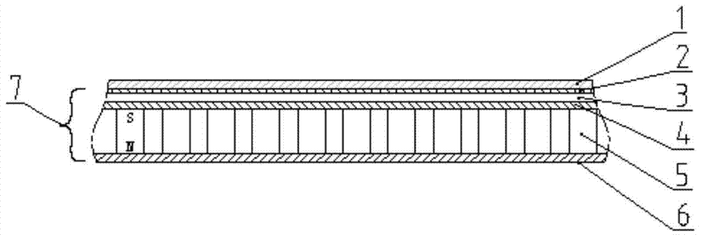
[0028] like image 3 As shown, a vacuum cathode arc source with arc spots all over the target surface discharge, including a rectangular flat target 1, the bottom surface of the flat target 1 is provided with a target base assembly 7, the flat target 1 and the target base assembly 7 are used Fasteners are tightly fitted and connected. In actual use, electrical insulation is maintained between the flat target 1 and the target base assembly 7; the target base assembly 7 is composed of cooling water channel components and magnetic circuit components stacked up and down; The flat cooling waterway 3 of the waterway metal upper cover sheet 2 and the cooling waterway metal bottom plate 4 is also provided with inlet and outlet ports. The cooling waterway metal upper cover sheet and the cooling waterway metal bottom plate are all made of red copper; the magnetic circ...


PUM

PropertyMeasurementUnit
diameteraaaaaaaaaa

Abstract

The invention provides a vacuum cathode arc source with discharge arc spots covering the target surface. Connection; the target base assembly is composed of a cooling water channel component and a magnetic circuit component stacked up and down; the cooling water channel component is a flat cooling water channel including a cooling water channel metal upper cover sheet and a cooling water channel metal bottom plate, and is provided with an inlet and an outlet; the magnetic circuit component is composed of magnetic poles The upper and lower end faces of a plurality of small cylindrical magnets are vertically arranged on a target base plate with the same pole and the same direction (the same magnetic pole faces the same direction). The invention has the following advantages: the discharge area is greatly increased, allowing to increase the target current several times, which is beneficial to greatly improve the deposition rate; the distributed arc discharge discharges almost on the entire target surface, so that the target surface is ablated more uniformly and the utilization rate of the target material is improved. ; Conducive to the heat conduction of the target surface and the water cooling, which is beneficial to improve the quality of the film.

Description

technical field [0001] The invention relates to a vacuum cathode arc source, in particular to a vacuum cathode arc source capable of covering the target surface with arc spots during discharge. Background technique [0002] Vacuum cathodic arc deposition is currently one of the mainstream ion coating technologies for preparing tool and mold hard protective films and decorative protective films. Because vacuum cathodic arc deposition has high ionization rate, high particle energy, good film / substrate bonding force, and deposition speed Fast, metal film, alloy film can be deposited, and various film systems such as nitride, carbide, oxide, carbonitride, and DLC can be synthesized by reaction plating, and the target position can be arranged arbitrarily. Special attention has been paid to the application of film deposition. A lot of work has been done on the development of vacuum cathode arc technology at home and abroad. The core technology is the structure and magnetic field d...

Claims


Application Information

Patent Timeline
Patent Type & Authority Patents(China)
IPC IPC(8): C23C14/32
Inventor 李志荣罗志明李志方袁镇海
Owner DONGGUAN HUICHENG VACUUM TECH
Why Eureka
Try Eureka