Steel coupling beam and concrete shear wall assembly type connecting structure reserving construction allowance

A technology of concrete shear wall and connection structure, which is applied in the direction of building structure and construction, can solve the problems of large axial and lateral errors and poor installation of components, achieve high node stiffness, improve bearing capacity, and avoid welding construction. time consuming effect

Inactive Publication Date: 2015-11-11
TONGJI UNIV +1
View PDF5 Cites 5 Cited by
  • Summary
  • Abstract
  • Description
  • Claims
  • Application Information

AI Technical Summary

Problems solved by technology

[0011] Aiming at the above problems, the present invention proposes a new type of assembled connection system, which uses end plates and high-strength bolts to solve the problem of on-site connection between steel connecting beams and concrete walls, and uses backing plates and oblong bolt holes to solve the problems caused by manufacturing errors. And the lateral error is large, the problem of not being able to install

Method used


Image

  • Steel coupling beam and concrete shear wall assembly type connecting structure reserving construction allowance
  • Steel coupling beam and concrete shear wall assembly type connecting structure reserving construction allowance
  • Steel coupling beam and concrete shear wall assembly type connecting structure reserving construction allowance

Examples


Embodiment Construction

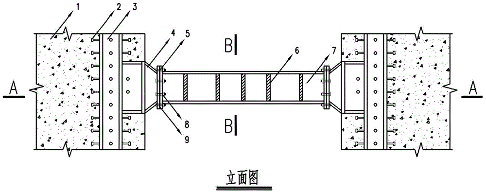
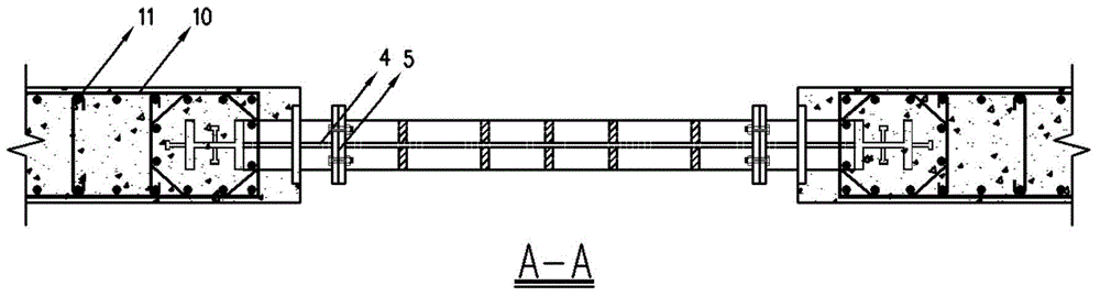
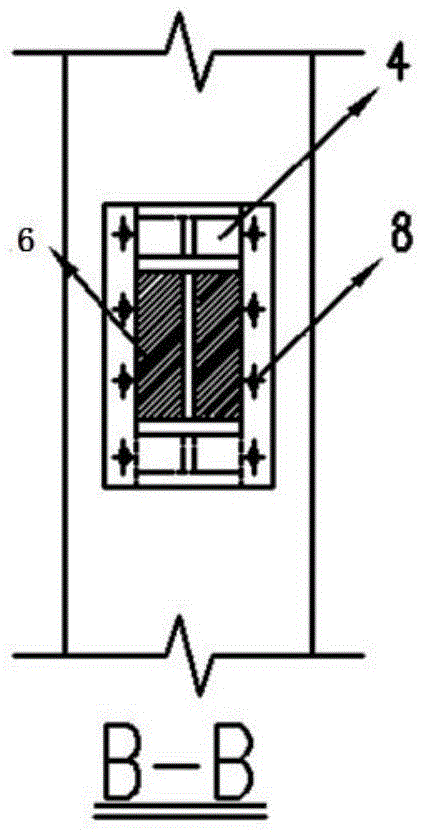
[0041] A continuous steel column is set in the concealed column area at the inner end of the concrete shear wall, and the steel column is welded to the corbel beam section at the position where the steel connecting beam is set. In order to improve the bending and shear resistance of the node connection area, artificial enlargement is reserved The section height of the corbel beam section. The section height of the beam section is retracted at the edge of the shear wall until it is equal to the section height of the steel connecting beam. The end of the beam must be welded with an end plate. Reserve a circular stirrup hole (the diameter of the hole is 5mm larger than the diameter of the stirrup in the concealed column of the concrete wall) in the web area of ​​the reserved corbel beam end to facilitate the binding of the stirrup in the concealed column area during on-site construction. The steel structure processing plant completes the production and welding of steel components i...


PUM


Abstract

A steel coupling beam and concrete shear wall assembly type connecting structure reserving construction allowance is characterized by consisting of a concrete shear wall, a steel reinforced concrete column embedded in the concrete shear wall, bracket steel beam sections, a steel coupling beam, two end plates and a base plate, wherein unequal-diameter round bolt holes are formed in the two end plates; the two end plates are parallel and level to the surface of the concrete shear wall and extend outwards; a reserved variable-section bracket beam section is welded to the steel reinforced concrete column buried in the shear wall; the end plates are respectively welded to ends of the bracket beam sections and the steel coupling beam; the base plate is inserted between the end plates so that the steel coupling beam is abutted between the bracket beam sections; the end plates are connected with the base plate by high-strength bolts through the oblique 45-degree oval bolt holes in two opposite directions; the base plate is provided with the oval bolt hole along the positive 45-degree direction; the plane view size of the base plate is smaller than the sizes of the end plates; and the end plate which is welded to the steel coupling beam is correspondingly provided with the oval bolt hole along the negative 45-degree direction. By the steel coupling beam and concrete shear wall assembly type connecting structure, changeability of the steel coupling beam is guaranteed, and construction is facilitated.

Description

Technical field [0001] The invention belongs to the technical field of assembly type combined structure connection, and specifically relates to a new combined system of section steel coupling beams and concrete shear walls. Background technique [0002] The structural form of the concrete bifurcated wall is a very important structural form, which has good rigidity and ductility. Among them, the steel coupling beam is not only simple in structure and convenient in construction, but also can provide a large shear force, can dissipate a large amount of energy under the action of an earthquake, and has a good control effect on the structure. Therefore, compared with the concrete coupling beam, it has Great superiority. [0003] During the installation and positioning of composite structural components, due to various uncertain factors during concrete pouring, the dimensional accuracy of the components is poor, and there is a big difference from the predetermined size, which will affec...

Claims


Application Information

Patent Timeline
Patent Type & Authority Applications(China)
IPC IPC(8): E04B1/38E04B1/58
Inventor 孙飞飞顾福霖李国强陈亮王新娣李春田
Owner TONGJI UNIV
Why Eureka
Try Eureka