A vertical axis hydroelectric generator

A hydraulic generator, vertical axis technology, applied in the direction of engine components, machines/engines, mechanical equipment, etc., can solve the problems of no commercial value, no use of ocean current energy, low power generation efficiency of power generation devices, etc., to achieve low power generation costs, Improve conversion efficiency and stabilize the environment

Inactive Publication Date: 2017-11-07
GUANGZHOU YATU NEW ENERGY TECH
View PDF8 Cites 0 Cited by
  • Summary
  • Abstract
  • Description
  • Claims
  • Application Information

AI Technical Summary

Problems solved by technology

At present, the device that utilizes ocean current energy to generate electricity generally converts energy for the first time through the wind wheel on the horizontal axis, then drives the hydraulic pump through the wind wheel for the second energy conversion, and finally uses the hydraulic pump to drive the generator for the third energy conversion. Conversion; because this type of ocean current energy generating device uses a horizontal axis wind rotor, each wind rotor can only drive one hydraulic pump, and each hydraulic pump can only drive one generator, resulting in the power generation of this type of generating device The efficiency is low, and the huge energy of ocean current energy has not been utilized to the maximum extent
From the field of power generation, this type of ocean current power generation device is only an ideal device for people, and has no commercial value, because the price of the electricity it generates is already higher than the current price of wind power generation

Method used


Image

  • A vertical axis hydroelectric generator
  • A vertical axis hydroelectric generator
  • A vertical axis hydroelectric generator

Examples


Embodiment Construction

[0033] The present invention will be further described below in conjunction with the accompanying drawings of the description.

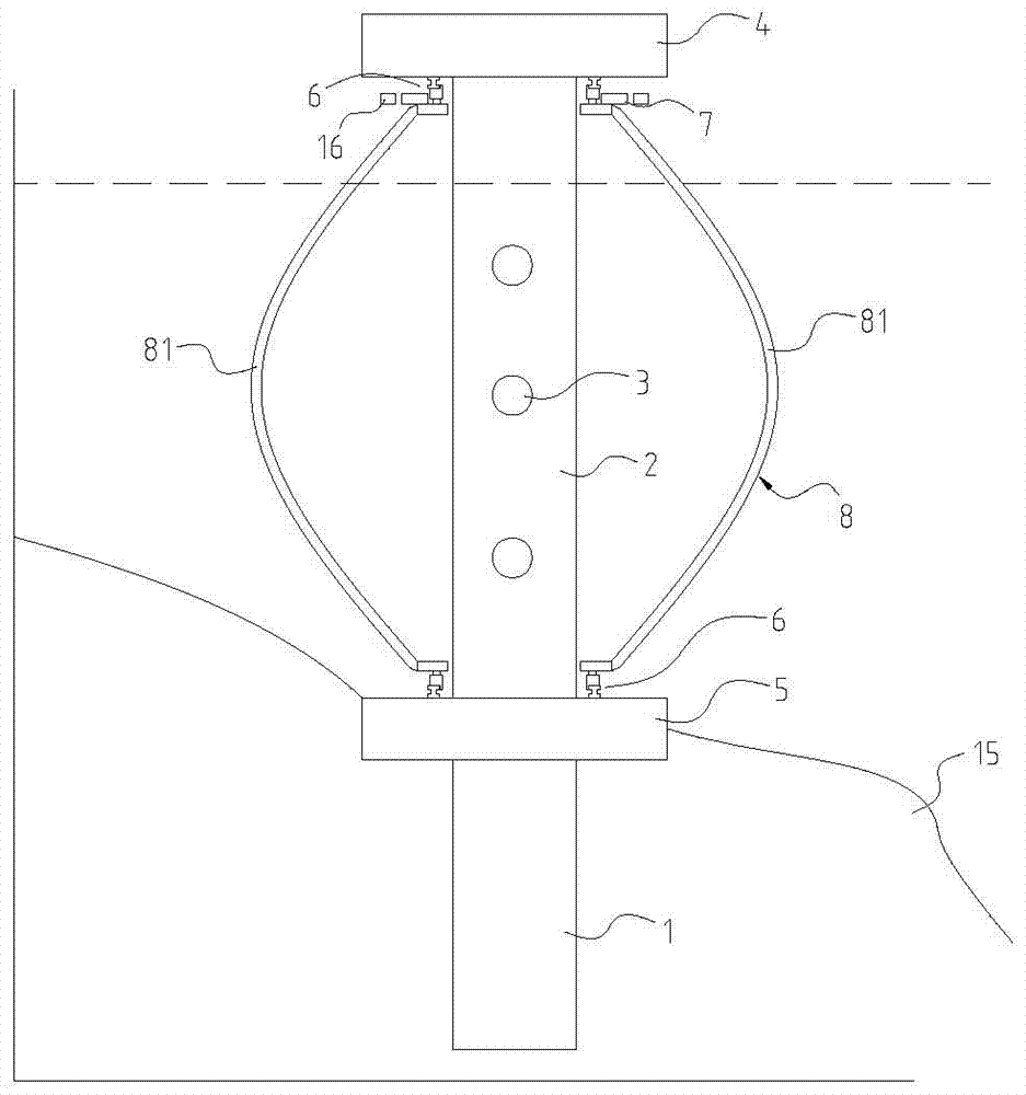
[0034] like figure 1 As shown, a vertical axis hydroelectric generator is mainly a device for generating electricity by using water current or ocean current, which can be applied to rivers or oceans. The vertical axis hydroelectric generator includes: a pile foundation 1, a tower column, an impeller 8, a bearing 6 and a generator set.

[0035] The pile foundation 1 goes deep into the seabed 15 through pile driving equipment, and the pile foundation 1 enables the huge tower to stand stably in the sea and resist the erosion of ocean currents.

[0036] like figure 1As shown, the tower column is arranged on the pile foundation 1, and the tower column includes an underwater platform 5, a support column 2 and an above-water platform 4. The underwater platform 5, supporting column 2 and above-water platform 4 are integrally molded by reinforced concrete,...


PUM


Abstract

A vertical shaft hydroelectric generator comprises a pile foundation, a tower column, an impeller, bearings and a generating unit. The tower column is arranged on the pile foundation. The tower column comprises an underwater platform, a supporting column and an overwater platform. The impeller is arranged in water. The upper end and the lower end of the impeller are connected through the bearings to enable the impeller to be connected outside the tower column in a pivoted manner. The bearings comprise annular tracks, annular installing bases and a plurality of wheels installed on the installing bases. The generating unit comprises a hydraulic control system, a generator and a power converting mechanism. The power converting mechanism comprises a gear disc located below the overwater platform. The gear disc embraces the supporting column and is connected with blades. The gear disc is meshed with a plurality of small gears. The hydraulic control system comprises a hydraulic motor, a constant-pressure liquid storage barrel and a plurality of hydraulic cylinders. The ends of pistons of the hydraulic cylinders are hinged to the small gears. The rotation of the small gears drives piston rods of the hydraulic cylinders to telescopically move in a reciprocating manner. The output ends of the hydraulic cylinders are connected with the constant-pressure liquid storage barrel. The output end of the constant-pressure liquid storage barrel is connected with the hydraulic motor. The hydraulic motor is in linkage with the generator. The hydraulic control system is utilized for carrying out energy conversion, and the multiple hydraulic cylinders can be arranged to improve the energy conversion efficiency.

Description

technical field [0001] The invention relates to ocean current energy power generation, in particular to a device for converting ocean current energy into vertical axis mechanical rotation and then generating electricity. Background technique [0002] Ocean current energy has high energy density, cleanliness, and strong predictability, and ocean current energy does not occupy valuable land resources for power generation. Therefore, the development and utilization of ocean current energy has far-reaching significance. At present, there are also many devices that use ocean current energy to generate electricity, such as a Chinese patent, a low-speed direct-drive hydraulic ocean current power generation device with a publication number of 103206334A, including an impeller, a quantitative hydraulic pump connected to the main shaft of the impeller, and a parallel connection with the quantitative hydraulic pump. And the variable hydraulic pump, variable hydraulic motor and generat...

Claims


Application Information

Patent Timeline
Patent Type & Authority Patents(China)
IPC IPC(8): F03B13/00F03B13/12
Inventor 邓允河
Owner GUANGZHOU YATU NEW ENERGY TECH
Why Eureka
Try Eureka