Stainless steel baking oven

A stainless steel and oven technology, applied in drying, drying machine, local stirring dryer, etc., can solve the problems of high labor intensity and low production efficiency of workers, and achieve low labor intensity, high production efficiency, and reliable sealing. Effect

Inactive Publication Date: 2015-11-11
ZHEJIANG YIYANG SOLAR TECH CO LTD
View PDF7 Cites 2 Cited by
  • Summary
  • Abstract
  • Description
  • Claims
  • Application Information

AI Technical Summary

Problems solved by technology

[0002] After the polysilicon is pickled to remove surface impurities, it needs to be dried in a polysilicon material oven. The existing ovens are all single-door ovens. Drying, the labor intensity of workers is high, and the production efficiency is low

Method used


Image

  • Stainless steel baking oven
  • Stainless steel baking oven

Examples


Embodiment 1

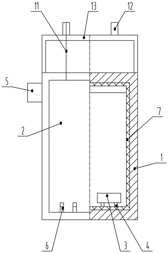
[0020] see Figure 1-2 , in the figure, the stainless steel oven of the present invention includes a stainless steel box body, a feed inlet and a discharge port are oppositely provided at both ends of the box body, a movable door 2 is respectively provided on the inlet and outlet and the discharge port, and a reciprocating door 2 is provided in the box body. The mobile trolley 3, the casters at the bottom of the trolley are slidingly matched with the corresponding parallel guide rails 4 provided at the bottom of the box body, and the box body is equipped with a controller 5 at the same time. The parallel guide rails extend outward from both ends of the box body, corresponding to the parallel guide rails, The bottom of the dodge door is matched with an avoidance groove 6, and an air curtain device 9 is respectively arranged on the top of both ends of the box body and behind the dodge door, and the air curtain device is provided with an air outlet 10 to communicate with the box b...

Embodiment 2

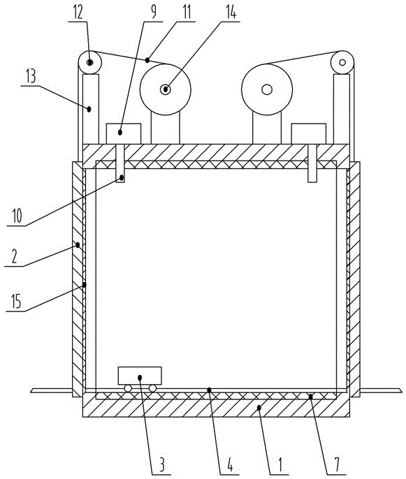
[0023] see figure 1 , 2 , in the figure, this embodiment is similar in structure to Embodiment 1, and the same numbers represent the same meaning, and the structurally identical parts will not be repeated here. The difference is that the movable door described in this embodiment is equipped with an automatic lifting device. The automatic lifting device includes slide rails, steel wire ropes 11, guide pulleys 12, brackets 13, and reels 14. The slide rails are located on both sides of the inlet and outlet of the box. There are two groups of pulleys, which are respectively placed on both sides of the dodge door, and the free end of the wire rope is connected with the dodge door. A sealing ring 15 is provided on the inner side of the movable door and the contact surface between the inlet and outlet of the box body. The movable door can be lifted and lowered automatically, which can reduce the labor intensity of workers and help improve production efficiency.

Embodiment 3

[0025] see figure 1 , 2 , in the figure, the structure of this embodiment is similar to that of Embodiment 1, and the same numbers represent the same meaning, and the same parts in the structure will not be repeated here. Plate 7 composition. There is an insulation layer on the box body to prevent heat loss and help to ensure a constant gradient temperature inside the box.


PUM


Abstract

The invention pertains to the technical field of production of polycrystalline silicon ingots, in particular to a stainless steel baking oven. The stainless steel baking oven comprises a stainless steel oven box, two ends of which are oppositely provided with a feeding port and a discharge port. The feeding port and the discharge port are provided with movable doors. A trolley, performing reciprocating motion, is arranged in the oven body. Trundles at the bottom of the trolley are connected with parallel guide rails correspondingly arranged at the bottom of the oven body in a slidably-matched mode. A controller is arranged on the oven body. The parallel guide rails extend outwardly from two ends of the oven body. Avoiding grooves, corresponding to the parallel guide rails, are arranged in the bottoms of the movable doors in a matching mode. Air curtain devices are arranged at tops of two ends of the oven body and behind the movable doors and downwardly provided with air outlets communicated with the interior of the oven body. The stainless steel baking oven has following beneficial effects: the stainless steel baking oven is simple in structure, convenient in operation and application, fine in thermal insulation performance and high in production efficiency and capable of maintaining the constant temperature of the oven body and has low labor intensity of workers so that the stainless steel baking oven is especially suitable for popularization and application.

Description

technical field [0001] The invention belongs to the technical field of polycrystalline silicon ingot production, in particular to a stainless steel oven. Background technique [0002] After the polysilicon is pickled to remove surface impurities, it needs to be dried in a polysilicon material oven. The existing ovens are all single-door ovens. Drying, the labor intensity of workers is high, and the production efficiency is low. In addition, when feeding and discharging materials, the external cold air will enter the box, and at the same time, the heat in the box will also be lost, so it is not easy to keep the temperature inside the box at a constant gradient. Contents of the invention [0003] The technical problem to be solved by the present invention is to overcome the deficiencies of the above-mentioned prior art, and provide a stainless steel oven that is easy to operate and use, can maintain a constant temperature inside the box, and has low labor intensity and high...

Claims


Application Information

Patent Timeline
Patent Type & Authority Applications(China)
IPC IPC(8): F26B9/06F26B25/00F26B25/12
Inventor 汪伟华
Owner ZHEJIANG YIYANG SOLAR TECH CO LTD
Why Eureka
Try Eureka