
Frequency domain depolarizer and depolarization method of Mach-Zehnder interferometer structure

A technology of interferometer and depolarizer, which is applied in the field of frequency domain depolarization to achieve the effect of convenient operation and high reliability

Inactive Publication Date: 2015-11-11
THE 41ST INST OF CHINA ELECTRONICS TECH GRP
View PDF6 Cites 3 Cited by
  • Summary
  • Abstract
  • Description
  • Claims
  • Application Information

AI Technical Summary

Problems solved by technology

The main problem at present is: due to the influence of its own structure, environment and other factors, the depolarization ability of traditional depolarizers such as extruded fiber type and Lyot has a certain limit, and the polarization degree of the output light after depolarization is below 0.5%. is not easy to achieve

Method used


Image

  • Frequency domain depolarizer and depolarization method of Mach-Zehnder interferometer structure
  • Frequency domain depolarizer and depolarization method of Mach-Zehnder interferometer structure
  • Frequency domain depolarizer and depolarization method of Mach-Zehnder interferometer structure

Examples


Embodiment 1

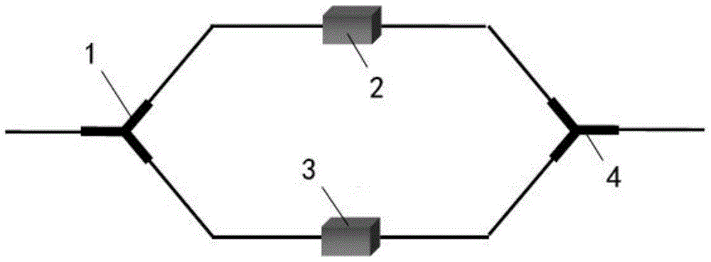
[0036] combine figure 1 As shown, a frequency-domain depolarizer with a Mach-Zehnder interferometer structure includes a polarization beam splitter 1 , a first attenuator 2 , a second attenuator 3 and a polarization beam combiner 4 .

[0037] The incident end of the polarizing beam splitter 1 is used to connect the light source to be depolarized; the outgoing end of the polarizing beam splitter 1 is divided into two paths, one path is connected to one end of the first attenuator 2, and the other path is connected to one end of the second attenuator 3 connect.

[0038] The incident end of the polarization beam combiner 4 is divided into two paths, the other end of the first attenuator 2 is connected to one path, and the other end of the second attenuator 3 is connected to the other path; the output end of the polarization beam combiner 4 is used as the final Depolarized light output terminal.

[0039] Wherein, the light source to be depolarized is a wide-spectrum light source...

Embodiment 2

[0045] combine figure 2As shown, a frequency-domain depolarization method of a Mach-Zehnder interferometer structure adopts a frequency-domain depolarizer of a Mach-Zehnder interferometer structure in the above-mentioned embodiment 1; wherein, the incident end of the polarization beam splitter 1 Connect the light source 5 to be depolarized, and the output end of the polarization beam combiner 4 is connected with a power meter 6; the frequency domain depolarization method includes the following steps:

[0046] a. Adjust the attenuation of the first attenuator 2 to the minimum and the attenuation of the second attenuator 3 to the maximum. At this time, the optical power reading of the power meter 6 is recorded as the first value I 1 ;

[0047] b. Adjust the attenuation of the first attenuator 2 to the maximum and the attenuation of the second attenuator 3 to the minimum. At this time, the optical power reading of the power meter 6 is recorded as the second value I 2 ;

[004...

Embodiment 3

[0053] combine image 3 As shown, a frequency-domain depolarization method of a Mach-Zehnder interferometer structure adopts a frequency-domain depolarizer of a Mach-Zehnder interferometer structure in the above-mentioned embodiment 1; wherein, the incident end of the polarization beam splitter 1 Connect the light source 5 to be depolarized, and the output end of the polarization beam combiner 4 is connected with a polarization degree tester 7; the frequency domain depolarization method includes the following steps:

[0054] a Adjust the attenuation of the first attenuator 2 and the second attenuator 3 to the minimum;

[0055] b. Gradually increase the attenuation of the first attenuator 2. If the reading of the degree of polarization tester 7 gradually decreases, then go to step c; if the reading of the degree of polarization increases gradually, then go to step d;

[0056] c Continue to increase the attenuation of the first attenuator 2 until the reading of the degree of po...


PUM


Abstract

The invention discloses a frequency domain depolarizer and depolarization method of a Mach-Zehnder interferometer structure. The frequency domain depolarizer comprises a polarization beam splitter, a first attenuator, a second attenuator and a polarization beam combiner. A light source to be depolarized is split into two paths of linear polarized light through the polarization beam splitter; light intensities of the two paths of linear polarized light are controlled by adjusting attenuation amount of the first attenuator and the second attenuator respectively; and the two paths of linear polarized light are combined through the polarization beam combiner and then, are output. When the light intensities of the two paths of linear polarized light output by the polarization beam combiner are same, a best depolarization effect is achieved, and the degree of polarization of depolarized light output by the polarization beam combiner is lower than 0.5%, so that high index requirements for the depolarizer in a plurality of application occasions of high-precision inertial navigation technology and Y waveguide high extinction ratio test and the like can be met; and besides, the frequency domain depolarizer is simple in structure and easy to integrate, convenient to operate and high in reliability.

Description

technical field [0001] The invention relates to a frequency domain depolarizer with a Mach-Zehnder interferometer structure and a frequency domain depolarization method with a Mach-Zehnder interferometer structure. Background technique [0002] A depolarizer is an important type of polarization device, which controls the polarization characteristics of the input light through certain technical means, thereby reducing the polarization degree of the output light. Depolarizers can be divided into time domain depolarization, frequency domain depolarization and air domain depolarization according to different principles. The time-domain depolarization mainly uses electro-optic modulation or acousto-optic modulation to make the polarization state of the incident light change at a higher speed than the detector response to achieve the effect of depolarization; the frequency-domain depolarization mainly weakens or eliminates the orthogonal polarization component of the input light. ...

Claims


Application Information

Patent Timeline
Patent Type & Authority Applications(China)
IPC IPC(8): G02B27/28
CPCG02B27/283
Inventor 李国超王恒飞应承平刘红元吴斌
Owner THE 41ST INST OF CHINA ELECTRONICS TECH GRP
Learn More