
Discrete vacuum-pumping transformer oil transfer system

A transformer oil transfer system technology, applied in the direction of transformer/inductor cooling, switchgear, electrical components, etc., can solve the problem of secondary pollution of transformer oil

Active Publication Date: 2015-11-11
STATE GRID SHANDONG ELECTRIC POWER
View PDF3 Cites 0 Cited by
  • Summary
  • Abstract
  • Description
  • Claims
  • Application Information

AI Technical Summary

Problems solved by technology

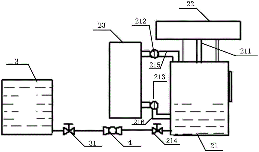
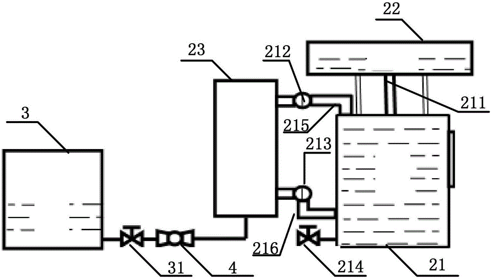
[0004] For this reason, the technical problem to be solved by the present invention is that in the prior art, during the maintenance process of the transformer, the internal transformer oil needs to be stored in an external oil tank, which is likely to cause secondary pollution of the transformer oil, thereby providing a transformer without Discrete evacuated transformer oil transfer system that can transfer transformer oil during maintenance using an external oil tank

Method used


Image

  • Discrete vacuum-pumping transformer oil transfer system
  • Discrete vacuum-pumping transformer oil transfer system
  • Discrete vacuum-pumping transformer oil transfer system

Examples


Embodiment 1

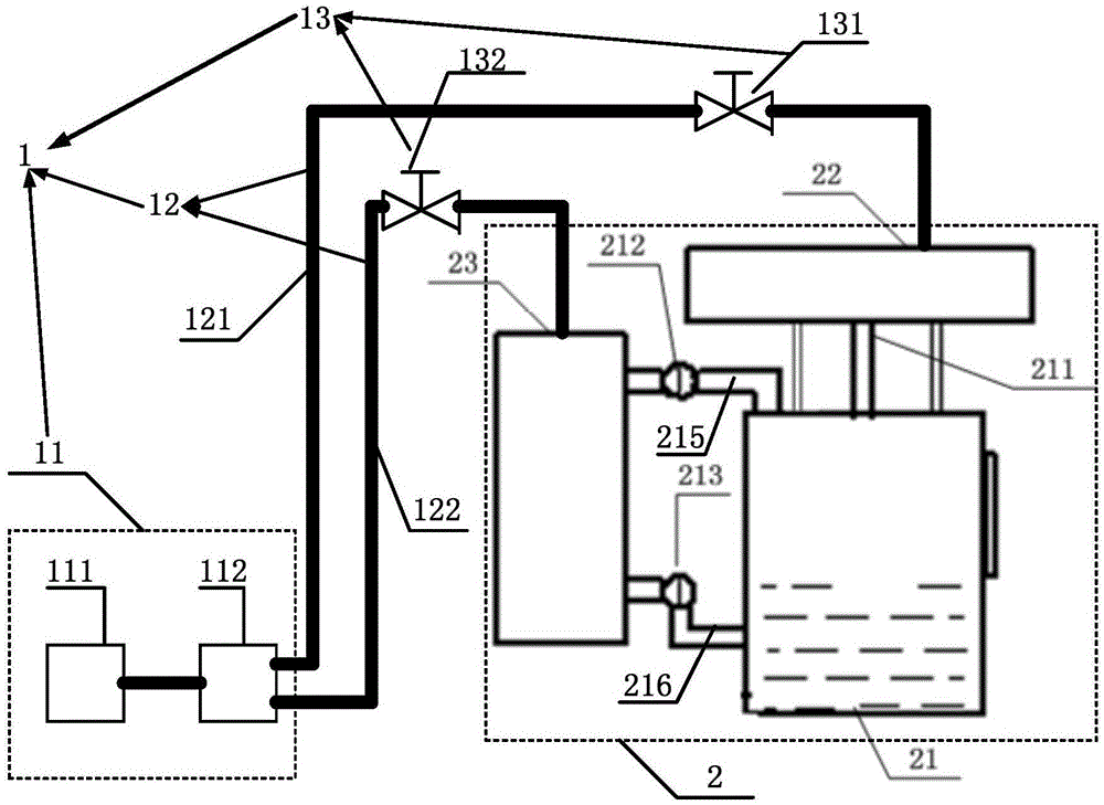
[0038] This embodiment provides a discrete vacuum transformer oil transfer system, such as image 3 As shown, a vacuum module 1 and a transformer 2 are included.

[0039] The transformer 2 includes a box body 21, an oil conservator 22 and a radiator 23. The box body 21 communicates with the oil conservator 22 through a first oil pipe 211; the box body 21 is connected through a second oil pipe 215 and a third oil pipe 215. The oil pipe 216 communicates with the radiator 23, the second oil pipe 215 is provided with a first butterfly valve 212, and the third oil pipe 216 is provided with a second butterfly valve 213, passing through the first butterfly valve 212 and the second The opening and closing of the butterfly valve 213 controls whether the tank 21 communicates with the radiator 23 .

[0040] The vacuum module 1 includes a vacuum device 11 , a connecting pipe 12 and a control valve 13 .

[0041] The connecting pipe 12 includes a first connecting pipe 121 , one end of whi...

Embodiment 2

[0053] On the basis of Embodiment 1, the discrete vacuum transformer oil transfer system described in this embodiment, such as Figure 4 As shown, as another optional implementation manner, the vacuuming module 1 further includes a radiator vacuuming device 11a, a radiator connecting pipe 12a, and a radiator control valve 13a.

[0054] One end of the radiator connecting pipe 12 a is in sealing communication with the radiator vacuum device 11 a , and the other end is in sealing communication with the radiator 23 .

[0055] The radiator control valve 13 a is arranged on the radiator connecting pipe 12 a for controlling whether the radiator vacuum device 11 a communicates with the radiator 23 or not.

[0056] As a preferred embodiment, in the discrete vacuum pumping transformer oil transfer system described in this embodiment, the radiator vacuum pumping device 11a includes a second vacuum pump 111a and a second separation tank 112a communicated with each other; One end of the r...


PUM


Abstract

The invention relates to a transformer oil transfer system. The transformer oil transfer system comprises a vacuumizing module and a transformer; the vacuumizing module comprises a vacuumizing device, a connecting pipe and a control valve; the connecting pipe comprises a first connecting pipe, one end of the first connecting pipe is communicated with the vacuumizing device in a sealed mode, and the other end of the first connecting pipe is communicated with an oil conservator of the transformer in a sealed mode; the control valve comprises a first control valve which is arranged on the first connecting pipe and used for controlling the vacuumizing device and the oil conservator to be communicated or not. According to the transformer oil transfer system, the transformer and the vacuumizing module are perfectly combined, the oil conservator of the transformer and a box body communicated with the oil conservator of the transformer are made in a negative pressure state by the vacuumizing device, and transformer oil in a radiator is transferred into the oil conservator and the box body; after maintenance, the negative pressure state is stopped, and the transformer oil flows back into the radiator again; in the whole maintenance process, the radiator can be made in a state without oil or a state with little oil by internally transferring the transformer oil, and secondary pollution to the transformer oil is avoided.

Description

technical field [0001] The invention relates to a transformer oil transfer system. Specifically, it is a discrete vacuumized transformer oil transfer system suitable for transferring transformer oil in the process of transformer maintenance. Background technique [0002] The role of the transformer in the power system is to transform the voltage to facilitate the transmission of power. After the voltage is boosted by the step-up transformer, the line loss can be reduced, the economy of power transmission can be improved, and the purpose of long-distance power transmission can be achieved. The step-down transformer can change the high voltage into the various levels of voltage required by the user to meet the needs of different users. The transformer is mainly composed of a box body, an insulating bushing, an oil conservator, a radiator, an iron core and a winding. The transformer box (that is, the oil tank) is filled with transformer oil, and the iron core and winding are...

Claims


Application Information

Patent Timeline
Patent Type & Authority Applications(China)
IPC IPC(8): H02B3/00H01F27/14
Inventor 郑强胡东张金良张鹏刘宁
Owner STATE GRID SHANDONG ELECTRIC POWER
Learn More