igbt protection circuit and protection method in stepper motor driver

A technology for stepping motors and protection circuits, applied to emergency protection circuit devices, electrical components, etc., can solve the problems of low IGBT judgment accuracy, short circuit overcurrent fault tolerance time, and short service life of IGBT, so as to reduce the number of protection times, The effect of improving life and stability and improving work efficiency

Inactive Publication Date: 2018-07-27
CHANGCHUN INST OF OPTICS FINE MECHANICS & PHYSICS CHINESE ACAD OF SCI
View PDF7 Cites 0 Cited by
  • Summary
  • Abstract
  • Description
  • Claims
  • Application Information

AI Technical Summary

Problems solved by technology

[0005] The present invention solves the technical problems of low judgment accuracy for IGBT protection in existing motor drivers, short circuit overcurrent fault tolerance time, short service life of IGBT and poor reliability, etc.

Method used


Image

  • igbt protection circuit and protection method in stepper motor driver
  • igbt protection circuit and protection method in stepper motor driver
  • igbt protection circuit and protection method in stepper motor driver

Examples


specific Embodiment approach 1

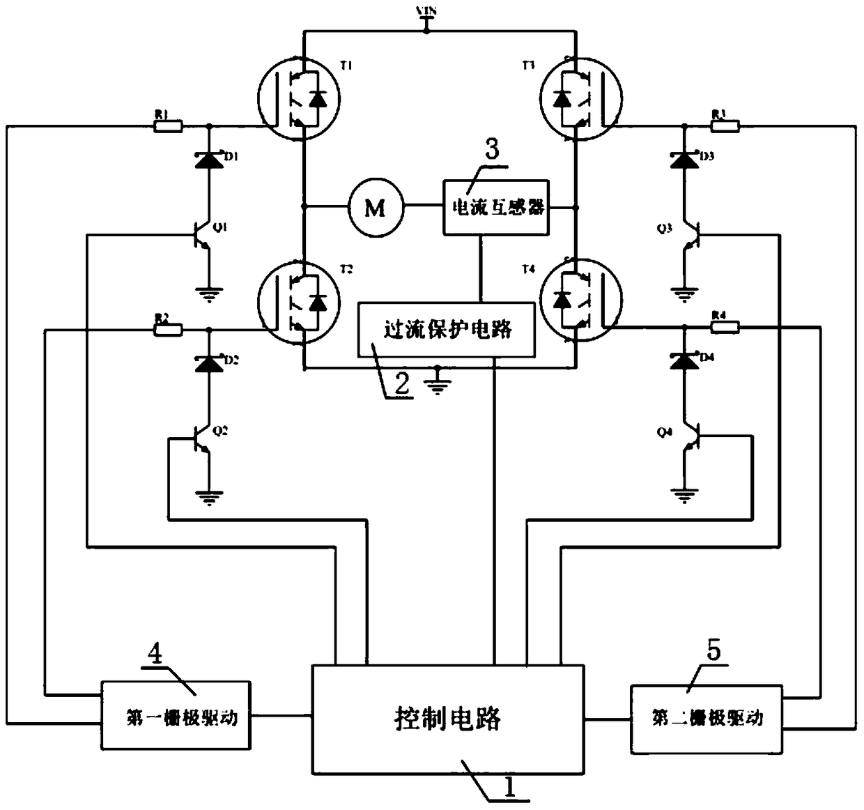
[0020] Specific implementation scheme 1, this scheme is specifically designed to protect the first type of overcurrent. Such as Figure 1 As shown, this scheme mainly includes control circuit 1, overcurrent protection circuit 2, current transformer 3, first gate driver 4, second gate driver 5, IGBTT1~T4, gate resistors R1~R4, gate stabilizer Diodes D1-D4 and transistors Q1-Q4. The control circuit 1 is connected to the first gate drive, the second gate drive and the bases of the transistors Q1~Q4, and the first gate drive and the second gate drive are connected to the IGBTs T1~T4 through the gate resistors R1~R4 The grid is connected, the collectors of the transistors Q1~Q4 are connected to the cathodes of the Zener diodes D1~D4, the anodes of the Zener diodes D1~D4 are connected to the gates of the IGBT T1~T4, and the IGBT T1~T4 and the stepping motor coil form an H-shaped PWM power In the conversion circuit, the current transformer 3 is connected in series in the motor coil...

specific Embodiment approach 2

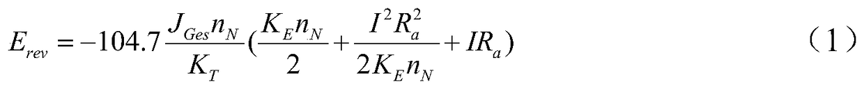
[0031] Specific embodiment 2. This embodiment is a specific example of protecting the second type of overcurrent: when the stepper motor is working, because the coil is an inductive element, it will store a certain amount of feedback energy. When the stepper motor brakes or When reversing, the feedback energy can be calculated as follows:

[0032]

[0033] where J Ges is the total inertia of the stepping motor, n N is the motor speed, K T is the motor torque coefficient, K E Is the back electromotive force coefficient of the motor, I is the braking current, R a is the internal resistance of the stepping motor coil, when the stepping motor rotates, R a Can be expressed as:

[0034] R a =ωL+r=9.549n N L+r (2)

[0035] Where ω is the angular velocity of the stepping motor, ω=9.549n N , L is the inductance of the stepping motor coil, r is the static internal resistance of the motor coil;

[0036]Let the highest voltage of the power supply be U s·max ,but:

[0037] u...


PUM


Abstract

The invention provides an IGBT protection circuit and a protection method in a stepping motor driver, relates to the technical field of motors, and solves the technical problems of low judgment accuracy, short circuit overcurrent fault tolerance time, short IGBT service life and poor reliability in the protection of the IGBT in the existing motor driver. . Including control circuit, overcurrent protection circuit, current transformer, gate drive, gate drive, IGBT, gate resistor, gate zener diode and triode. The control circuit is connected to the gate drive and the base of the triode, the gate drive is connected to the gate of the IGBT through the gate resistor, the collector of the triode is connected to the cathode of the Zener diode, the anode of the Zener diode is connected to the gate of the IGBT, and the current transformer It is connected in series in the motor coil, the output end of the current transformer is connected with the input end of the overcurrent protection circuit, and the output end of the overcurrent protection circuit is connected with the control circuit. The invention reduces the protection times of the overcurrent current and improves the working efficiency of the driver.

Description

technical field [0001] The invention relates to the technical field of motors, in particular to an IGBT overcurrent protection method and protection circuit in a stepping motor driver. Background technique [0002] IGBT (Insulated Gate Bipolar Transistor, insulated gate bipolar transistor) is a common electronic device in stepper motor drivers, used for PWM (Pulse-Width Modulation, pulse width modulation) power conversion of the driver circuit. In operation, when the internal current of the PWM power conversion circuit of the stepper motor driver commutates and the stepper motor brakes or reverses, the inductive element inside the stepper motor will release the reverse current, causing the current in the IGBT to increase sharply. If the current value exceeds the safe working area of ​​the IGBT, the IGBT will be damaged. At this time, the stepper motor driver is required to turn off the IGBT for protection. [0003] At present, the protection method of IGBT mainly uses delay...

Claims


Application Information

Patent Timeline
Patent Type & Authority Patents(China)
IPC IPC(8): H02H7/08H02H7/20
Inventor 高慧斌马泽龙
Owner CHANGCHUN INST OF OPTICS FINE MECHANICS & PHYSICS CHINESE ACAD OF SCI
Why Eureka
Try Eureka