Brake chopper power unit

A brake chopper and power unit technology, applied in the direction of output power conversion device, DC power input conversion to DC power output, electrical components, etc., can solve the inconvenient parts replacement, storage, large space occupation, and power circuit structure Complexity and other issues, to reduce design and operation maintenance costs, improve operational stability and life, and shorten the design cycle

Active Publication Date: 2017-08-04
CRRC YONGJI ELECTRIC CO LTD
View PDF4 Cites 0 Cited by
  • Summary
  • Abstract
  • Description
  • Claims
  • Application Information

AI Technical Summary

Problems solved by technology

The disadvantages of this technology are: 1) the structure of the power circuit is complicated, and it is not conducive to maintenance and replacement when the power circuit fails; Low; the entire main circuit structure is bloated, the electrical clearance distance is required to be large, and the space occupied is large; 3) When the power increases, it is difficult or impossible to expand capacity
The main disadvantage of this technology is: although two sets of main circuits are installed on the same radiator, it does not adopt a completely simplified design, which is not convenient for replacement and storage of components, and the cost of the product is relatively high
The disadvantages of this technology are: the braking power unit and the chopper power unit work independently, occupy a large volume on the limited locomotive or subway space, are not easy to install, and the design cost is high

Method used


Image

  • Brake chopper power unit
  • Brake chopper power unit
  • Brake chopper power unit

Examples


Embodiment Construction

[0047] The present invention will be further explained below in conjunction with the drawings:

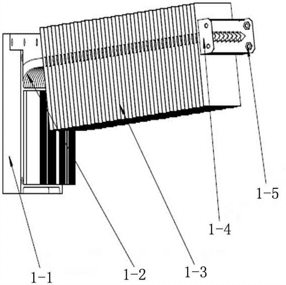
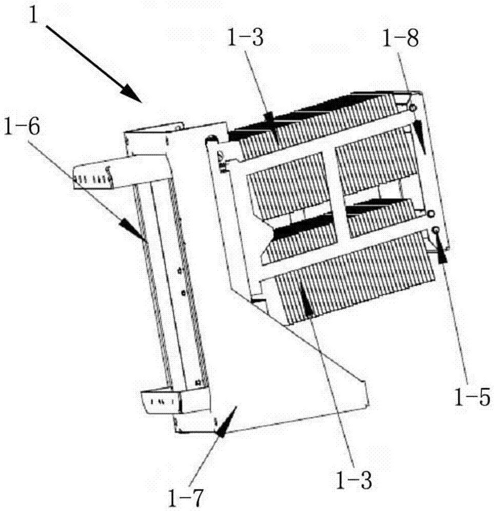
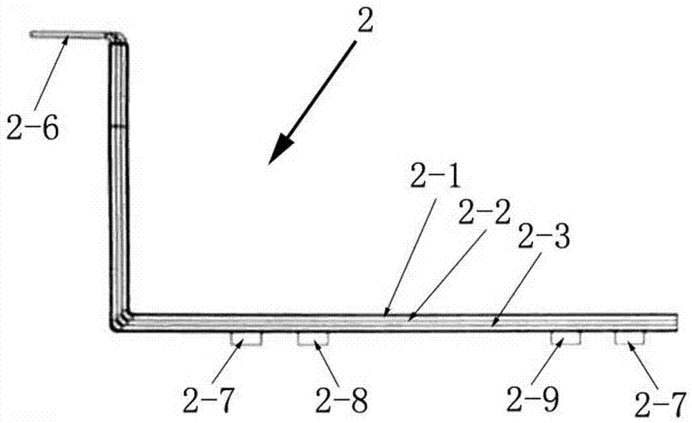
[0048] Such as Figure 1 to Figure 7 As shown, a new type of braking chopper power unit includes a radiator 1 and a composite busbar 2; the radiator 1 includes two upper and lower sections of heat pipe radiator units, and each section of the heat pipe radiator unit includes a heat dissipation substrate 1- 1. Several L-shaped heat pipes 1-2 and several fins 1-3, among which, the vertical pipes of several L-shaped heat pipes 1-2 are arranged in parallel with the heat dissipation substrate 1-1 and are directly embedded and fixed side by side on the heat dissipation substrate 1 -1, a number of radiating fins 1-3 are inserted and fixed one by one adjacent to the horizontal tubes of several L-shaped heat pipes 1-2, and the ends of the horizontal tubes of several L-shaped heat pipes 1-2 are installed and fixed together Mounting board 1-4, the two sides of the mounting board 1-4 are crimped ...


PUM


Abstract

The present invention is a novel brake chopper power unit, including a radiator, a composite busbar and a brake chopper main circuit. The power unit adopts a laminated modular design. Each power device in the circuit is installed on the surface of the radiator, and each power device connects all components of the brake chopper main circuit through a composite busbar and inputs and outputs externally. The invention adopts a simplified main circuit and a convenient and flexible circuit connection technology to unify the components and facilitate the expansion of the power unit; adopts a modular design of a stacked structure, saves space, facilitates maintenance and replacement, and reduces maintenance costs; The main circuit electrical technology reduces the stray inductance of the main circuit loop, improves the reliability of the main circuit, and completely avoids the difficulty of detouring cables in a narrow space. The structure is compact, the volume is reduced, and the design cost is reduced.

Description

Technical field [0001] The invention relates to the field of electrical technology, in particular to a new type of braking chopper power unit. Background technique [0002] The main function of the subway traction system is to take power from the intermediate DC loop, and after inverting through the three-phase circuit composed of IGBTs on the traction inverter power unit, it supplies power to the train's traction motor, drives the subway vehicle to run, and at the same time uses braking and chopping The power unit solves the problem that the intermediate voltage is too high during the braking process or when the grid voltage fluctuates, which damages the IGBT devices. The subway traction system is the core of subway vehicles and the source of power for subway vehicles. Since the running time between subway stations is only a few minutes, this requires the entire subway traction system to respond quickly, start and stop quickly, and be stable. , Which puts forward higher require...

Claims


Application Information

Patent Timeline
Patent Type & Authority Patents(China)
IPC IPC(8): H02M3/00H05K7/20
Inventor 陈宏高永军牛勇刘金燕程琳
Owner CRRC YONGJI ELECTRIC CO LTD
Why Eureka
Try Eureka