Overhead Rigid Catenary Temperature Compensation Device

A temperature compensation device, rigid contact technology, applied in overhead lines, power rails, etc., can solve the problems of high installation accuracy, affecting driving safety, and heavy maintenance workload, ensuring the height difference of the contact line and avoiding the phenomenon of jamming , to ensure the effect of the quality of the flow

Active Publication Date: 2017-09-15
CHINA RAILWAY HIGH SPEED ELECTRIFICATION EQUIP CORP LTD
View PDF2 Cites 1 Cited by
  • Summary
  • Abstract
  • Description
  • Claims
  • Application Information

AI Technical Summary

Problems solved by technology

[0002] The overhead rigid suspension busbar power supply system will freely expand and contract due to thermal expansion and contraction in the line. At present, the disconnected anchor section joint structure is mainly used for temperature compensation (patent number: ZL 200420043748.1). The two busbars at the joint are arranged in parallel, separated by 200 ~ 300mm, high installation accuracy requirements, complex layout, this structure is mainly suitable for operating speed requirements not greater than 120km / h
There are also expansion elements used for temperature compensation, but due to the structural problems and heavy weight of the expansion elements currently used, arcing and discharge phenomena are prone to occur during line use, and the maintenance workload is large, which affects driving safety and has not been widely promoted. application

Method used


Image

  • Overhead Rigid Catenary Temperature Compensation Device
  • Overhead Rigid Catenary Temperature Compensation Device
  • Overhead Rigid Catenary Temperature Compensation Device

Examples


Embodiment Construction

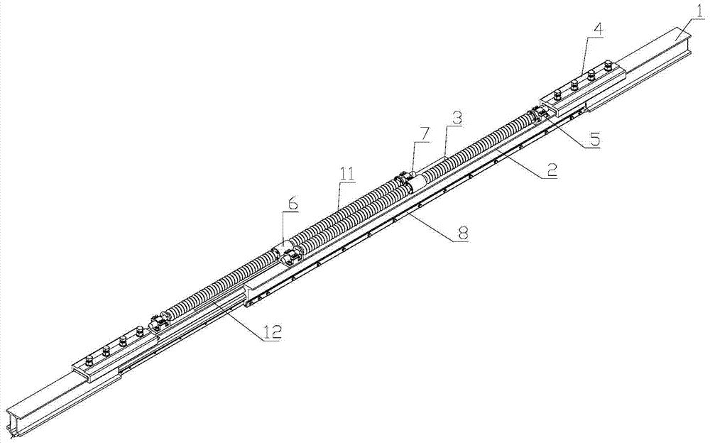
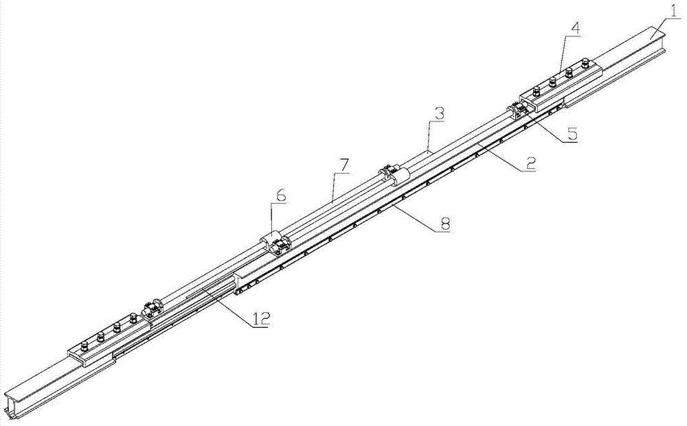
[0023] combined with Figure 1-7 Specific embodiments of the present invention will be described in detail.

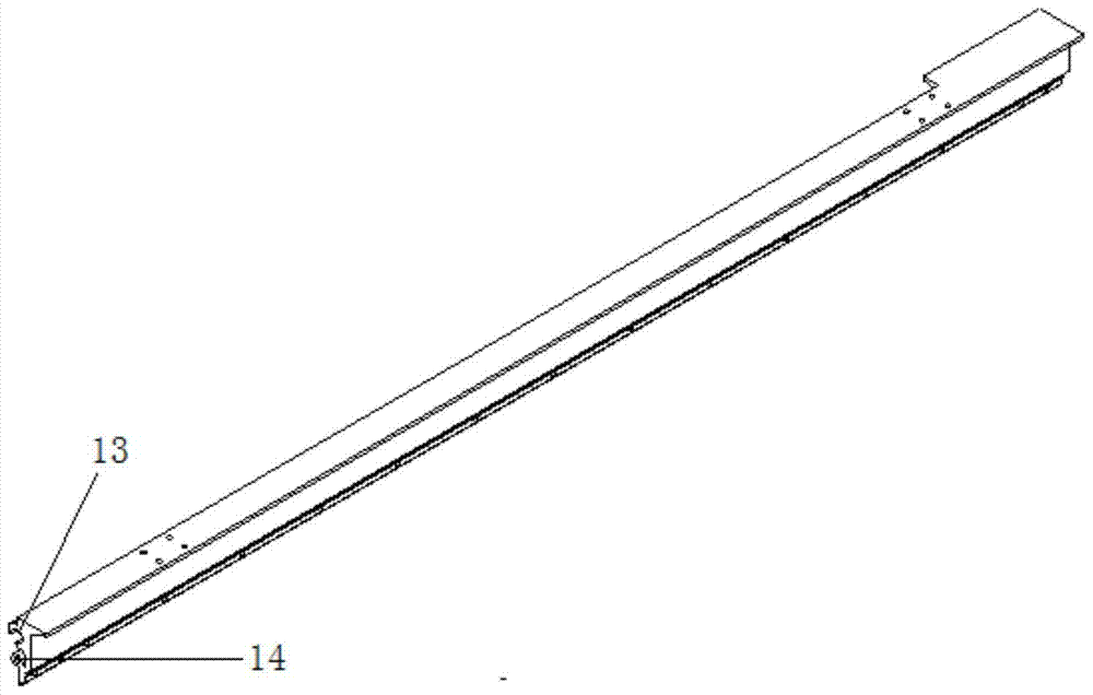
[0024] An overhead rigid catenary temperature compensation device, comprising a left sliding guide rail 2 and a right sliding guide rail 3, the outer ends of the left sliding guide rail 2 and the right sliding guide rail 3 are respectively connected and fixed to the bus bars 1 at both ends through the bus bar outsourcing joint 4, And the top cross section of the outer end of the left sliding guide rail 2 and the right sliding guide rail 3 is the same as the top cross section of the bus bar 1, so as to ensure the reliability of the connection with the bus bar. The inner sides of the left sliding guide rail 2 and the right sliding guide rail 3 are all formed with slideways 13 and slide rails 14, and the two slideways 13 and the two slide rails 14 are staggered up and down, and the slide rails 14 are inserted in the opposite sides. In the side slideway 13, the left slidi...


PUM


Abstract

An overhead rigid catenary temperature compensation device, the outer ends of the left sliding guide rail and the right sliding guide rail are respectively connected and fixed with the bus bars at both ends; The slide rail is inserted in the slideway on the opposite side, and the two sliding guide rails are connected together so that they can slide relatively freely; the lower end of the outer side of the two sliding guide rails is formed with a contact wire slot through the length, and the contact wire slot and the bus bar connected thereto The contact line slot at the lower end corresponds to the slot; the top surfaces of the two sliding guide rails are fixed with guide rods through guide supports and parallel guide seats, and the middle section of guide rods penetrates into the parallel guide seats on the opposite side to follow The two sliding guide rails slide freely. The invention is installed in the overhead rigid catenary system, which compensates the thermal expansion and contraction of the system due to temperature changes, realizes good electrical continuity and smooth transition between the anchor sections, ensures the stable operation of the locomotive, and improves the safety and reliability of locomotive operation .

Description

technical field [0001] The invention belongs to the technical field of rail transit rigid catenary, and in particular relates to an overhead rigid catenary temperature compensation device. Background technique [0002] The overhead rigid suspension busbar power supply system will freely expand and contract due to thermal expansion and contraction in the line. At present, the disconnected anchor section joint structure is mainly used for temperature compensation (patent number: ZL 200420043748.1). The two busbars at the joint are arranged in parallel, separated by 200 ~ 300mm, high installation accuracy requirements, complex layout, this structure is mainly suitable for operating speed requirements not greater than 120km / h. There are also expansion elements used for temperature compensation, but due to the structural problems and heavy weight of the expansion elements currently used, arcing and discharge phenomena are prone to occur during line use, and the maintenance worklo...

Claims


Application Information

Patent Timeline
Patent Type & Authority Patents(China)
IPC IPC(8): B60M1/26
CPCB60M1/26B60M1/30
Inventor 林建李增勤刘娟杨旭尧龚建刚郝新娟李立邓相龙王红喜
Owner CHINA RAILWAY HIGH SPEED ELECTRIFICATION EQUIP CORP LTD
Why Eureka
Try Eureka