Integral wall and construction process thereof

An integral, wall panel technology, applied in the direction of walls, building materials, building components, etc., can solve the problems of wasting energy, polluting the environment, poor flatness, etc., achieving the effect of simple construction process operation, simple overall structure, and improved stability.

Active Publication Date: 2015-11-18
HEFEI DESIGN & RES INST LLC OF COAL IND
View PDF6 Cites 15 Cited by
  • Summary
  • Abstract
  • Description
  • Claims
  • Application Information

AI Technical Summary

Problems solved by technology

[0002] In the field of building construction, generally the frame structure is made first, including load-bearing beams and columns, and then a filling wall (brick wall) is built between the load-bearing beams and columns to play the role of enclosure and separation, but the brick wall has the following disadvantages: 1. The construction is slow (a skilled bricklayer builds a wall of 7-8 square meters in 8 hours a day); 2. The wall surface is uneven and the flatness is poor; 3. The thickn

Method used


Image

  • Integral wall and construction process thereof
  • Integral wall and construction process thereof
  • Integral wall and construction process thereof

Examples


Example Embodiment

[0034] Example 1

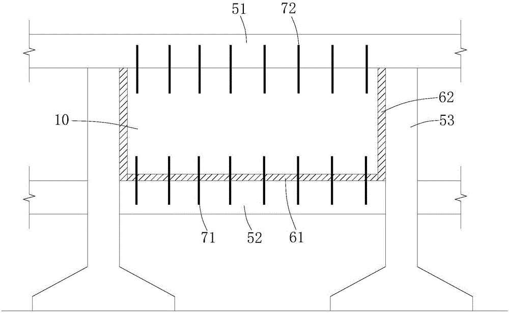
[0035] see figure 1 , figure 2 , image 3 , Figure 4 , Figure 5 and Image 6 .

[0036] The integral wall includes a load-bearing frame composed of an upper load-bearing beam 51, a lower load-bearing beam 52, and two load-bearing columns 53 connected between the upper load-bearing beam 51 and the lower load-bearing beam 52, and the integral wall also includes a prefabricated wall panel 10, The prefabricated wall panel 10 is installed between the upper load-bearing beam 51, the lower load-bearing beam 52 and two load-bearing columns 53, and the lower side of the prefabricated wall panel 10 passes through the first vibration isolation pad 61 and the lower load-bearing beam. 52, the left and right sides of the prefabricated wall panel 10 are respectively connected to the inner surfaces of the two load-bearing columns 53 through the second shock-isolating pad 62, and the lower load-bearing beam 52 is connected to the prefabricated wall panel 10 are pro...

Example Embodiment

[0044] Example 2

[0045] see Figure 7 .

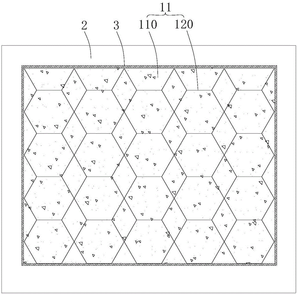
[0046] This embodiment is similar to Embodiment 1, so only the differences will be described. Their difference lies in that: the plurality of fiber units 120 are arranged in honeycomb and filled in the foamed concrete matrix 110 . The honeycomb structure is a very high-strength structure, and this arrangement can also improve the strength of the present invention.

Example Embodiment

[0047] Example 3

[0048] see Figure 8 .

[0049] This embodiment is similar to Embodiment 1, so only the differences will be described. Their difference is that: the prefabricated wall panel 10 is provided with a hole 4 for installing a door, the hole wall of the hole 4 is covered with a hole wall reinforced frame plate 41, and the hole wall reinforced frame plate 41 is made of reinforced concrete production. According to the design requirements, some filling walls need to open holes 4 for installing doors, and the set hole wall reinforcement frame plate 41 can not only enhance the strength and stability of the holes 4, but also provide a A stable mount. In this embodiment, the lower end of the hole 4 extends to the lower side of the prefabricated wall panel 10 to form an opening, and the upper end of the hole 4 is close to the upper side of the prefabricated wall panel 10, so that the upper and lower ends of the hole wall reinforced frame plate 41 are in contact with th...


PUM


Abstract

The invention provides an integral wall which comprises a load-bearing frame and a prefabricated wallboard. The load-bearing frame is composed of an upper load-bearing beam, a lower load-bearing beam and two load-bearing uprights connected between the upper load-bearing beam and the lower load-bearing beam, the lower side face of the prefabricated wallboard is joined with the upper side face of the lower load-bearing beam through a first shock-isolating pad, the left side face of and the right side face of the prefabricated wallboard are joined with the inner side faces of the load-bearing uprights through second shock-isolating pads respectively, multiple first connecting ribs are arranged between the lower load-bearing beam and the prefabricated wallboard, and multiple second connecting ribs are arranged between the upper load-bearing beam and the prefabricated wallboard. The integral wall is simple in structure, easy to construct, high in load-bearing capacity and good in anti-seismic performance. The invention further provides a construction process of the integral wall. The construction process is simple in operation and easy to carry out, stability of the integral wall can be guaranteed, and positions where the integral wall is connected with the load-bearing beams and the load-bearing uprights are less prone to cracking.

Description

technical field [0001] The invention relates to the field of building materials, in particular to an integral wall and its construction technology. Background technique [0002] In the field of building construction, generally the frame structure is made first, including load-bearing beams and columns, and then a filling wall (brick wall) is built between the load-bearing beams and columns to play the role of enclosure and separation, but the brick wall has the following disadvantages: 1. The construction is slow (a skilled bricklayer builds a wall of 7-8 square meters in 8 hours a day); 2. The wall surface is uneven and the flatness is poor; 3. The thickness of the brick wall mortar joints is different, and the outer wall The fullness of the joint mortar is not enough, which will easily lead to leakage of the external wall; 4. The wall and the frame column and the floor beam and slab belong to the secondary lap joint, and cracks are prone to occur at the junction; 5. The wa...

Claims


Application Information

Patent Timeline
IPC IPC(8): E04B2/64E04B1/98E04C2/38E04C2/26
Inventor 沈佳欣丁大勇
Owner HEFEI DESIGN & RES INST LLC OF COAL IND
Why Eureka
Try Eureka