Mobile multifunctional steaming and showering room
A multi-functional and mobile technology, applied in heating methods, bathing devices, non-electric variable control, etc., can solve problems such as leakage, material deformation, and rot, and achieve improved leakage prevention performance, improved thermal conductivity, and improved use. The effect of longevity
- Summary
- Abstract
- Description
- Claims
- Application Information
AI Technical Summary
Problems solved by technology
Method used
Image
Examples
Embodiment 1
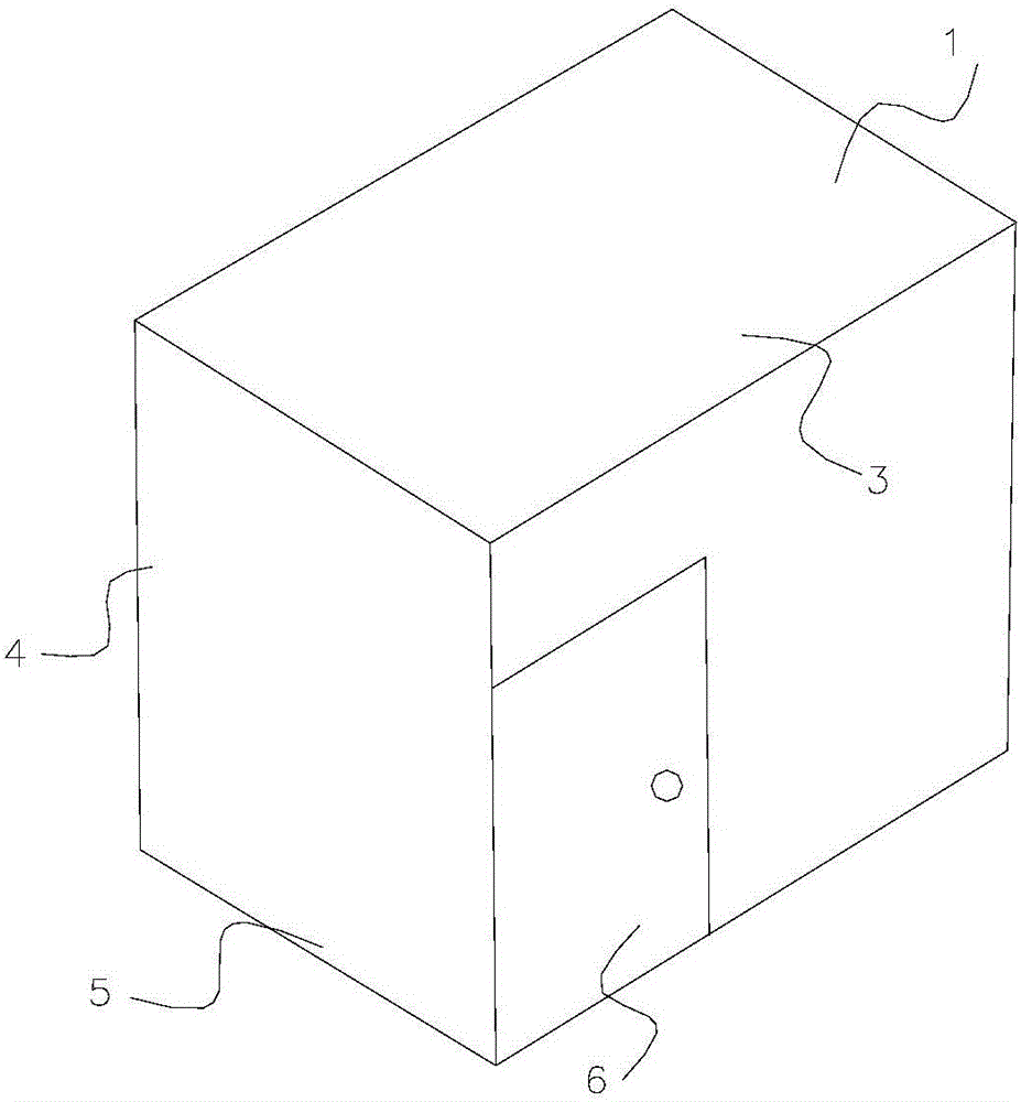
[0037] figure 1 It is a structural schematic diagram of a mobile multifunctional sweat steaming shower room in an embodiment of the present invention. The mobile multifunctional sweat steaming shower room includes a room body 1 and a shower head 2 arranged inside the room body 1 . The sweat steaming room 1 is a closed space formed by a ceiling 3 , four walls 4 and a floor 5 , and the walls 4 are provided with a door 6 and a control system 7 .
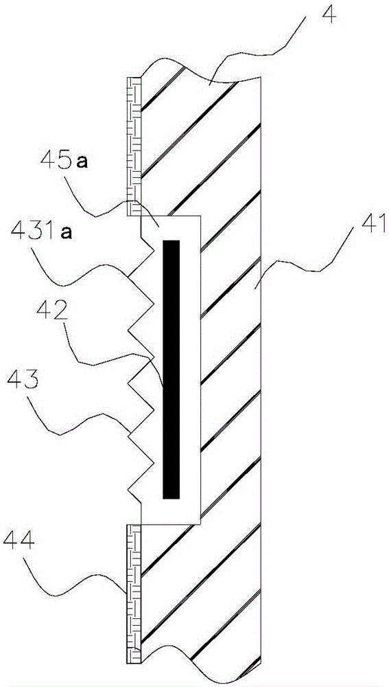
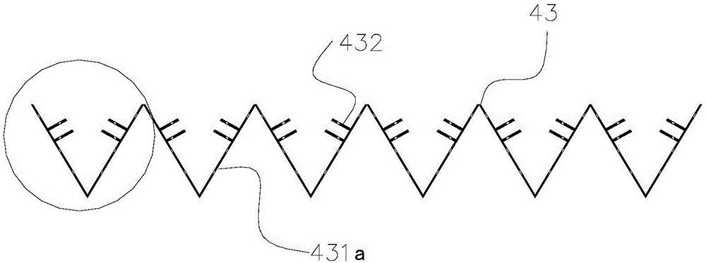
[0038] figure 2 It is a structural schematic diagram of the wall body in the embodiment of the present invention. The wall body 4 is divided into an insulating layer 41, a heating layer 42, a heat conducting layer 43, and a protective layer 44 from the outside to the inside. The insulating layer 41 is provided with a heat conducting groove 45a for accommodating the heating layer 42. The heat conducting groove 45a of this embodiment is It is square and set on the surface of the thermal insulation layer 41 , and the opening of the hea...
Embodiment 2
[0056] Figure 7 It is a structural schematic diagram of the wall body of Embodiment 2 of the present invention. Body of wall 4 is divided into insulation layer 41, heating layer 42, heat conduction layer 43 and protective layer 44 from outside to inside, and insulation layer 41 is provided with the heat conduction groove 45b that is used for accommodating heating layer 42, and the opening of heat conduction groove 45b uses heat conduction layer 43 for encapsulation. Compared with Embodiment 1, the difference of this embodiment is that the heat conduction groove 45b is arranged on the outside of the insulation layer 41. The purpose of this design makes the insulation layer 41 at the heating layer 42 have sufficient thickness, which can improve the insulation effect of the insulation layer 41. , so as to achieve the purpose of saving energy.
Embodiment 3
[0058] Figure 8 It is a structural schematic diagram of the thermal insulation layer in Example 3 of the present invention. Compared with the above-mentioned embodiment, the difference of this embodiment is that the heat-insulation layer 41 is designed as a detachable structure formed by inserting several sub-insulation layers 411 . The sub-insulation layer 411 has a small area and can be produced by using leftover materials. It is also convenient to replace the problematic sub-insulation layer 411 in a targeted manner. At the same time, the detachable structure also facilitates the transfer and movement of the steam room.
PUM
| Property | Measurement | Unit |
|---|---|---|
| thickness | aaaaa | aaaaa |
| thickness | aaaaa | aaaaa |
| thickness | aaaaa | aaaaa |
Abstract
Description
Claims
Application Information
 - R&D
- Intellectual Property
- Life Sciences
- Materials
- Tech Scout
- Unparalleled Data Quality
- Higher Quality Content
- 60% Fewer Hallucinations
Browse by: Latest US Patents, China's latest patents, Technical Efficacy Thesaurus, Application Domain, Technology Topic, Popular Technical Reports.
© 2025 PatSnap. All rights reserved.Legal|Privacy policy|Modern Slavery Act Transparency Statement|Sitemap|About US| Contact US: help@patsnap.com


