
Panorama three-dimensional laser sensor data calibration method and apparatus

A technology of three-dimensional laser and calibration method, which is applied in the field of environmental perception, and can solve problems such as data errors, ignoring internal parameters of three-dimensional lasers, and calibration of three-dimensional laser sensors

Inactive Publication Date: 2015-11-18
SHENYANG INST OF AUTOMATION - CHINESE ACAD OF SCI +1
View PDF6 Cites 24 Cited by
  • Summary
  • Abstract
  • Description
  • Claims
  • Application Information

AI Technical Summary

Problems solved by technology

[0005] Literature (Jesús Morales, Jorge L. Martínez, Anthony Mandow, Antonio J. Reina, Alejandro -BoterandAlfonsoGarcía-Cerezo, "BoresightCalibrationofConstructionMisalignmentsfor3DScannersBuiltwitha2DLaserRangefinderRotatingonItsOpticalCenter", Sensors, 14(11), 20025-20040, 2014.) Using the Nelder-Mead method to optimize the flatness and area of ​​the plane data, and calibrate the coordinates of the 2D laser sensor relative to the 3D data The two rotation angles of the system, although relatively accurate 3D data can be obtained, but because some internal parameters of the 3D laser are ignored, when there is an installation error, a certain amount of data error will still be introduced
Similarly, the literature (Gu Xiaojie, Bu Chunguang, Chen Cheng, Zhou Junzhe, "Research on Design and Calibration Method of 3D Laser Ranging System", Journal of Shenyang University of Technology, 33(5), 10-14, 47, 2014) only considered 3D laser Some internal parameters of the sensor cannot be used as a general method to calibrate various 3D laser sensors

Method used

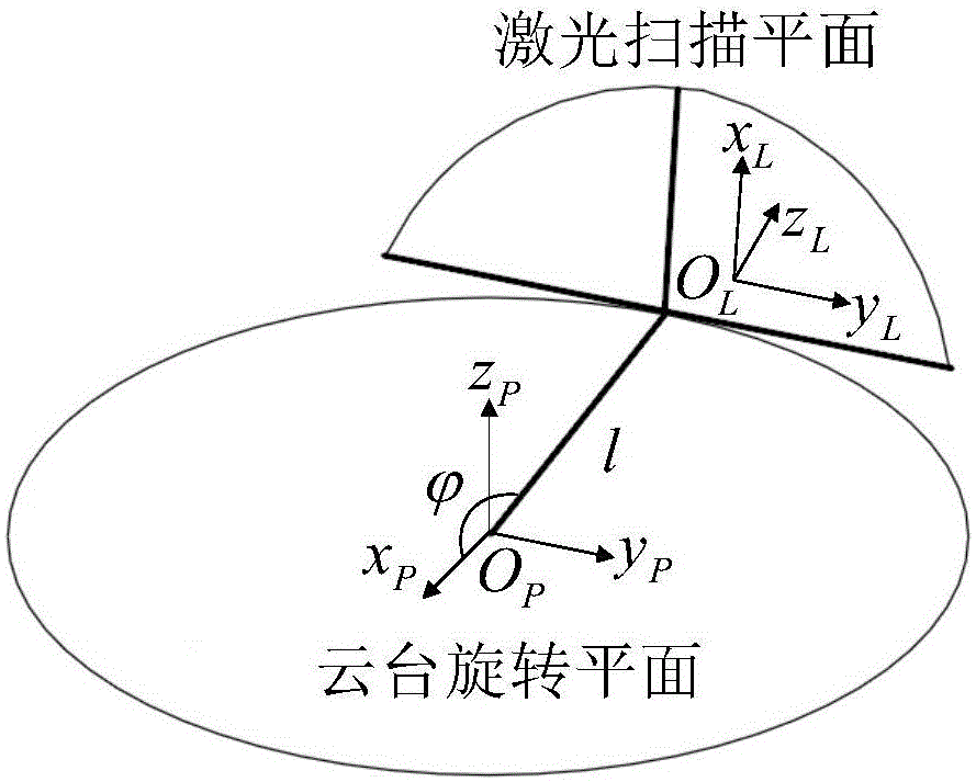
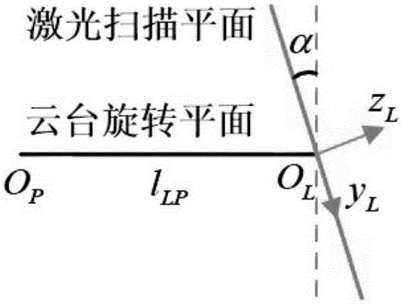
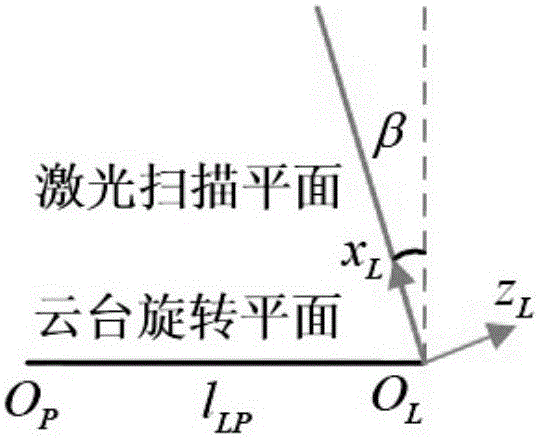

Image

  • Panorama three-dimensional laser sensor data calibration method and apparatus
  • Panorama three-dimensional laser sensor data calibration method and apparatus
  • Panorama three-dimensional laser sensor data calibration method and apparatus

Examples


Embodiment Construction

[0052] The present invention will be further described in detail below in conjunction with the accompanying drawings and embodiments.

[0053] The biggest innovation of the present invention is that it fully considers the angle and position errors that may exist in the installation process, and is suitable for parameter calibration of various panoramic three-dimensional laser sensors. For this reason, the present invention uses three angle parameters between the two-dimensional laser coordinate system and the three-dimensional laser coordinate system and one deflection center distance parameter as the parameters to be calibrated, through plane fitting, laser data binarization, and corner point extraction processing, from The characteristic points belonging to the calibration device are extracted from the two parts of the three-dimensional laser data collected, and the iterative optimization method is used to solve the parameters to be calibrated, so as to obtain the angle and p...


PUM


Abstract

The invention relates to a panorama three-dimensional laser sensor data calibration method and apparatus. The apparatus includes a three-dimensional laser sensor and a calibration device. The method includes the following steps: firstly, dividing scan data of a two-dimensional laser sensor into two parts on average on the basis of the positive portion and the negative portion of a yL axis, then forming a laser scan plane, and forming two pieces of space three-dimensional point cloud data by the positive and negative laser data of the yL axis when a rotary holder drives the two-dimensional laser sensor to rotate 360 degrees; secondly, extracting laser data characteristic points needed by calibration from the two pieces of space three-dimensional point cloud data; and thirdly, optimizing distances among the laser points in the two pieces of space three-dimensional point cloud data, and then obtaining a calibration parameter. The problems of uncontrollable human errors and long time caused by hand-operated click matching are solved, factors that are likely to affect the data precision are fully considered, the calibration precision of the sensor is improved, and the universality of the calibration method is improved.

Description

technical field [0001] The invention belongs to the technical field of environmental perception, in particular to a method and device for improving the accuracy of panorama data collected by a three-dimensional laser ranging system, and in particular to a method and device for calibrating panoramic three-dimensional laser sensor data. Background technique [0002] The laser sensor is an active sensor with strong anti-interference ability, can provide accurate depth information, can describe the geometric characteristics of the environment in detail, and directly and quickly obtain the 3D model of the environment, so it occupies a dominant position in 3D environment perception. It has great application value in engineering surveying and other fields. At present, there are many manufacturers selling 3D laser inspection systems in the world, such as Riegl in Austria, Leica in Switzerland, Topcon in Japan, Faro in the United States, etc. These sensors are expensive and often hav...

Claims


Application Information

Patent Timeline
IPC IPC(8): G01D18/00G01S7/497
Inventor 赵忆文卜春光庄严闫飞高英丽
Owner SHENYANG INST OF AUTOMATION - CHINESE ACAD OF SCI
Learn More