

Laser cladding bonding-based cutter and workpiece diffusion couple making method
A technology of laser cladding and diffusion couple, applied in the field of mechanical and material science, to reduce the experimental cost and shorten the experimental period.
- Summary
- Abstract
- Description
- Claims
- Application Information
AI Technical Summary
Problems solved by technology
Method used
Image

Examples
Embodiment 1
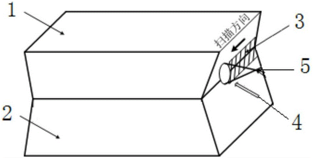
[0035] Embodiment 1: as figure 1 As shown, a method for preparing a diffusion couple based on laser cladding bonding of a cutting tool and a workpiece comprises the following steps:
[0036] A. Select the cemented carbide tool YG6 from Zhuzhou Cemented Carbide Factory as the tool sample 1, and use the gray cast iron HT250 for the cylinder block of the Weichai Power Engine as the workpiece sample 2.
[0037] B. Cut the tool sample 1 into a trapezoidal structure of 16mm×8mm×6mm by wire cutting, and cut the workpiece sample 2 into a trapezoidal structure of 16mm×8mm×4mm by wire cutting;
[0038] C. Cut the sample obtained in step A and step B for the second time, so that the two samples after cutting can form at least one groove or cavity after lamination, which is used to place the cladding powder, so that the two samples can be in a metallurgical state. hold together firmly;
[0039] D. Carry out rough grinding and fine grinding on the grinding machine for the surface to be b...
PUM
 Abstract
Description
Claims
Application Information