A mems optical switch

A technology of optical switch and output optical fiber, which is applied in the field of optical switches, can solve the problems of unfavorable reduction of driving displacement, unfavorable packaging and integration, etc., and achieve the effects of improving packaging and integrable scalability, improving electrostatic driving ability, and reducing system stiffness

Active Publication Date: 2018-06-01
BEIJING INST OF AEROSPACE CONTROL DEVICES
View PDF5 Cites 0 Cited by
  • Summary
  • Abstract
  • Description
  • Claims
  • Application Information

AI Technical Summary

Problems solved by technology

The reflective optical switch (publication number CN 10106372A) disclosed by Japan Aviation Electronics Industry Co., Ltd. adopts a fixed micromirror and a movable micromirror driven by an electrostatic comb to realize optical path switching. The movable micromirror forms an acute angle with the input optical fiber, which is not conducive to Reduce the driving displacement; its input and output fibers are arranged on the same side, but at a certain angle to each other, which is not conducive to packaging and integration

Method used


Image

  • A mems optical switch
  • A mems optical switch

Examples


Embodiment Construction

[0025] The present invention will be described in detail below in conjunction with the accompanying drawings.

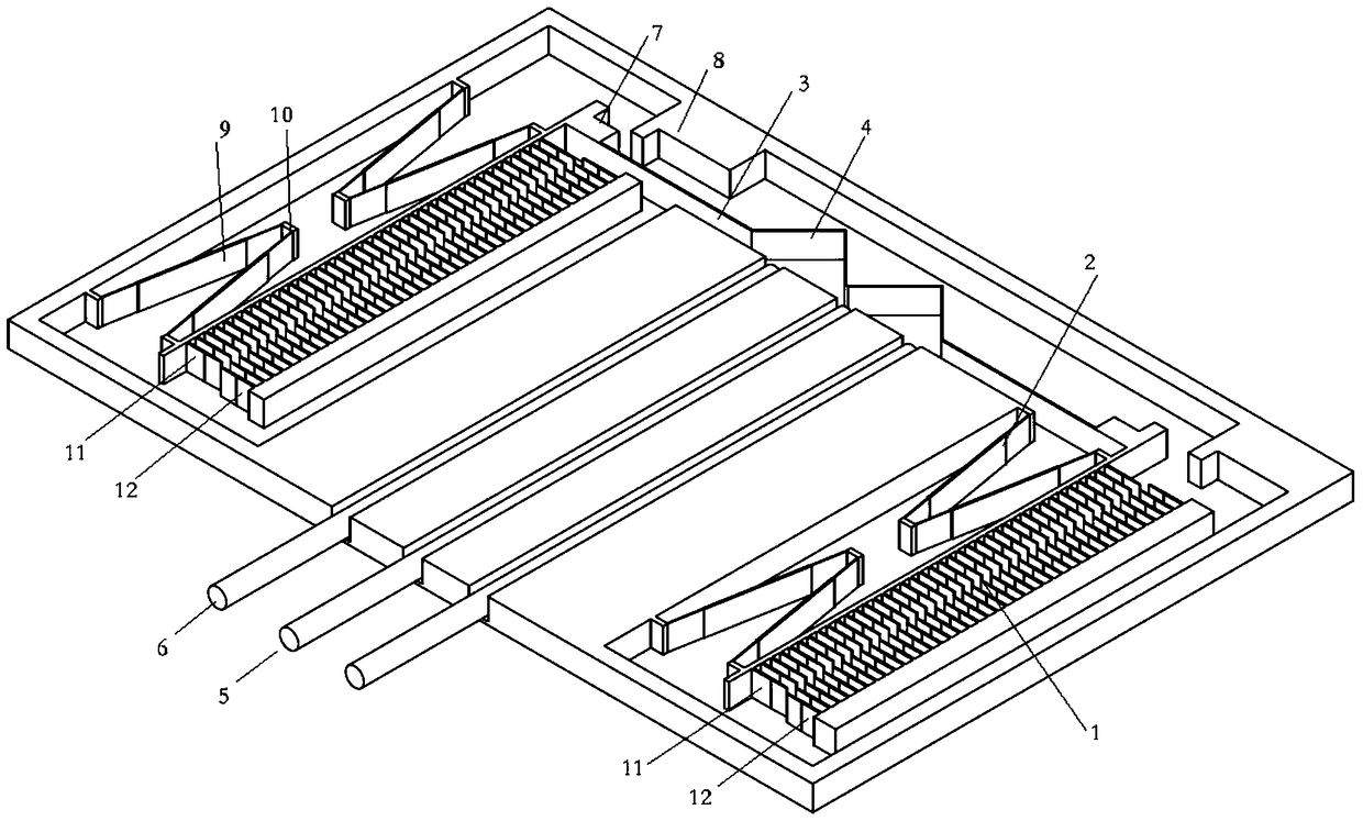
[0026] Such as figure 1 As shown, a MEMS optical switch includes a drive module 1, a folded beam 2, a support beam 3, a micro-mirror 4, an input optical fiber 5 and an output optical fiber 6, wherein the micro-mirror 4 is located in the middle of the support beam 3, and the support beam 3 Both ends of the drive module 1 are provided, and the side of the drive module 1 is provided with a folding beam 2;

[0027] The drive module 1 arranged along the direction of the support beam 3 is an electrostatic comb drive structure, which is a wedge-shaped comb. Compared with the traditional rectangular comb, the wedge-shaped comb is beneficial to increase the drive displacement and reduce the drive voltage; the movable The non-overlapping initial arrangement of comb teeth and fixed comb teeth is beneficial to improve the lateral stability of the driving structure and increase ...


PUM


Abstract

The invention discloses an MEMS optical switch. The MEMS optical switch comprises drive modules, folding beams, a supporting beam, a micro reflector, an input fiber and output fibers. The micro reflector is positioned in the middle of the supporting beam, the drive modules are disposed on two sides of the supporting beam, and the side surface of each drive module is provided with the corresponding folding beams. The drive modules arranged consequentially along the supporting beams are of static comb-tooth drive structures formed by movable comb teeth and fixed comb teeth. The micro reflector is an M-shaped reflector, and the middle part of the micro reflector is a tip. Input light from the input fiber can be transmitted to the different output fibers through reflection of different positions of the micro reflector by changing the relative position between the input fiber and the tip in the middle part of the M-shaped micro reflector. Under the effect of the same drive voltage, a left drive end and a right drive end generate electrostatic force facing the same direction, and the resultant force of the two drive ends is twice as much as the drive force generated by a conventional single-end drive structure. Therefore, the static drive capability of the MEMS optical switch is improved, and the drive voltage can be reduced.

Description

technical field [0001] The invention relates to an optical switch, in particular to a MEMS optical switch which realizes the change of the propagating direction of input light through reflection, thereby realizing the switching function. The invention is applied to optical fiber communication systems, distributed optical fiber sensing, optical fiber measurement systems and laser ignition systems to realize switching of optical signals and optical energy. Background technique [0002] An optical switch is an optical path conversion device with one or more gate ports, and its function is to switch optical signals and energy, so as to realize the function of physical switch or logical addressing. In the optical communication network, the main functions are used for multiple monitors, LAN, multiple light sources, detectors and conversion lines for protecting Ethernet. In the optical fiber test system, it is mostly used for optical fiber, optical fiber equipment testing and netw...

Claims


Application Information

Patent Timeline
Patent Type & Authority Patents(China)
IPC IPC(8): G02B6/35
CPCG02B6/3518G02B6/3584
Inventor 梅崴邢朝洋胡启方刘福民李昌政
Owner BEIJING INST OF AEROSPACE CONTROL DEVICES
Why Eureka
Try Eureka