Optical orientation device and optical orientation method

A technology of light alignment and polarized light, applied in the field of light alignment

Inactive Publication Date: 2015-11-18
USHIO DENKI KK
View PDF4 Cites 4 Cited by
  • Summary
  • Abstract
  • Description
  • Claims
  • Application Information

AI Technical Summary

Problems solved by technology

[0004] The size of the photo-alignment film increases alo

Method used


Image

  • Optical orientation device and optical orientation method
  • Optical orientation device and optical orientation method
  • Optical orientation device and optical orientation method

Examples


Embodiment Construction

[0099] Next, modes for carrying out the invention of the present application (hereinafter referred to as embodiments) will be described.

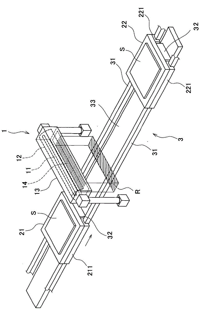
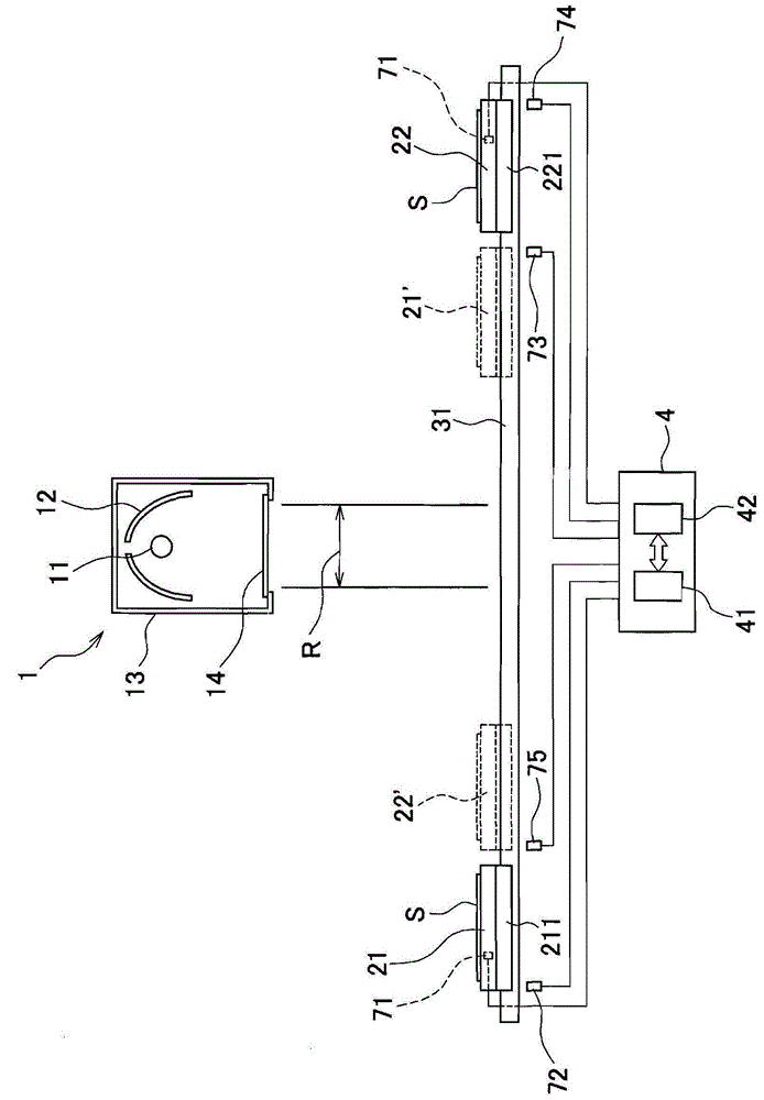
[0100] figure 1 It is a perspective schematic view of the photo-alignment device which concerns on 1st Embodiment. figure 1 The shown photo-alignment device includes: an irradiation unit 1 that irradiates polarized light toward a set irradiation region R; stages 21 and 22 on which a substrate S is placed; The stage moving mechanism 3 that irradiates polarized light to the liquid crystal substrate S on the stages 21 and 22 .

[0101] The irradiation unit 1 irradiates polarized light in a substantially rectangular pattern, and the area of ​​the pattern is an irradiation region R. FIG. The irradiation area R is set as an area within the horizontal plane.

[0102] The stage moving mechanism 3 is a mechanism for moving the stages 21 and 22 so as to pass through the irradiation area R described above. In this embodiment, the tables 21 and 22 ...


PUM


Abstract

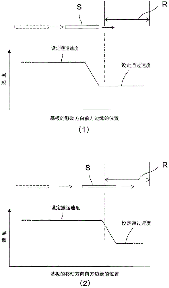
An optical orientation device and an optical orientation method are provided. In the field of optical orientation, production rate and quality are to be improved. Two workbenches (21, 22) are provided with a baseplate (S). By use of a workbench moving mechanism (3), the two workbenches (21, 22) are alternately reciprocated to go through an irradiated area (R) irradiated by polarized light sent from an irradiation unit (1).A control unit (4) is used for controlling the workbench moving mechanism (3) and keeps a low speed or a constant setting passing through speed when the workbenches (21, 22) pass through the irradiated area (R).The first workbench (21) moves between the first baseplate carrying and recovering position and the irradiated area (R)at a high speed or a setting carrying speed; The second workbench (22) moves between the second baseplate carrying and recovering position and the irradiated area (R) at a high speed or a setting carrying speed.

Description

technical field [0001] The invention of the present application relates to a technique of photo-alignment known as a method for obtaining an alignment film. Background technique [0002] In recent years, when obtaining an alignment film of a liquid crystal display element including a liquid crystal panel, and an alignment layer of a viewing angle compensation film, a technique called photo-alignment for aligning by light irradiation has been adopted. Hereinafter, films and layers that are oriented by light irradiation are collectively referred to as photo-alignment films. In addition, "orientation" and "orientation processing" refer to giving directionality to a certain property of an object. [0003] Photo-alignment is performed by irradiating polarized light to a film for photo-alignment films (hereinafter referred to as a film material). The film material is made of resin such as polyimide, and the film material is irradiated with polarized light polarized in a desired ...

Claims


Application Information

Patent Timeline
IPC IPC(8): G02F1/1337
CPCG02F1/133788
Inventor 石井一正
Owner USHIO DENKI KK
Why Eureka
Try Eureka