Lip skin sector and method and apparatus for forming lip skin sector

A molding device, sector technology, applied in ground devices, transportation and packaging, aircraft power devices, etc., to achieve uniform flow, reduce manual workload, and reduce the risk of material deformation or deterioration

Active Publication Date: 2019-02-22
ROHR INC
View PDF4 Cites 0 Cited by
  • Summary
  • Abstract
  • Description
  • Claims
  • Application Information

AI Technical Summary

Problems solved by technology

Known deep drawing processes are not suitable...

Method used


Image

  • Lip skin sector and method and apparatus for forming lip skin sector
  • Lip skin sector and method and apparatus for forming lip skin sector
  • Lip skin sector and method and apparatus for forming lip skin sector

Examples


Embodiment Construction

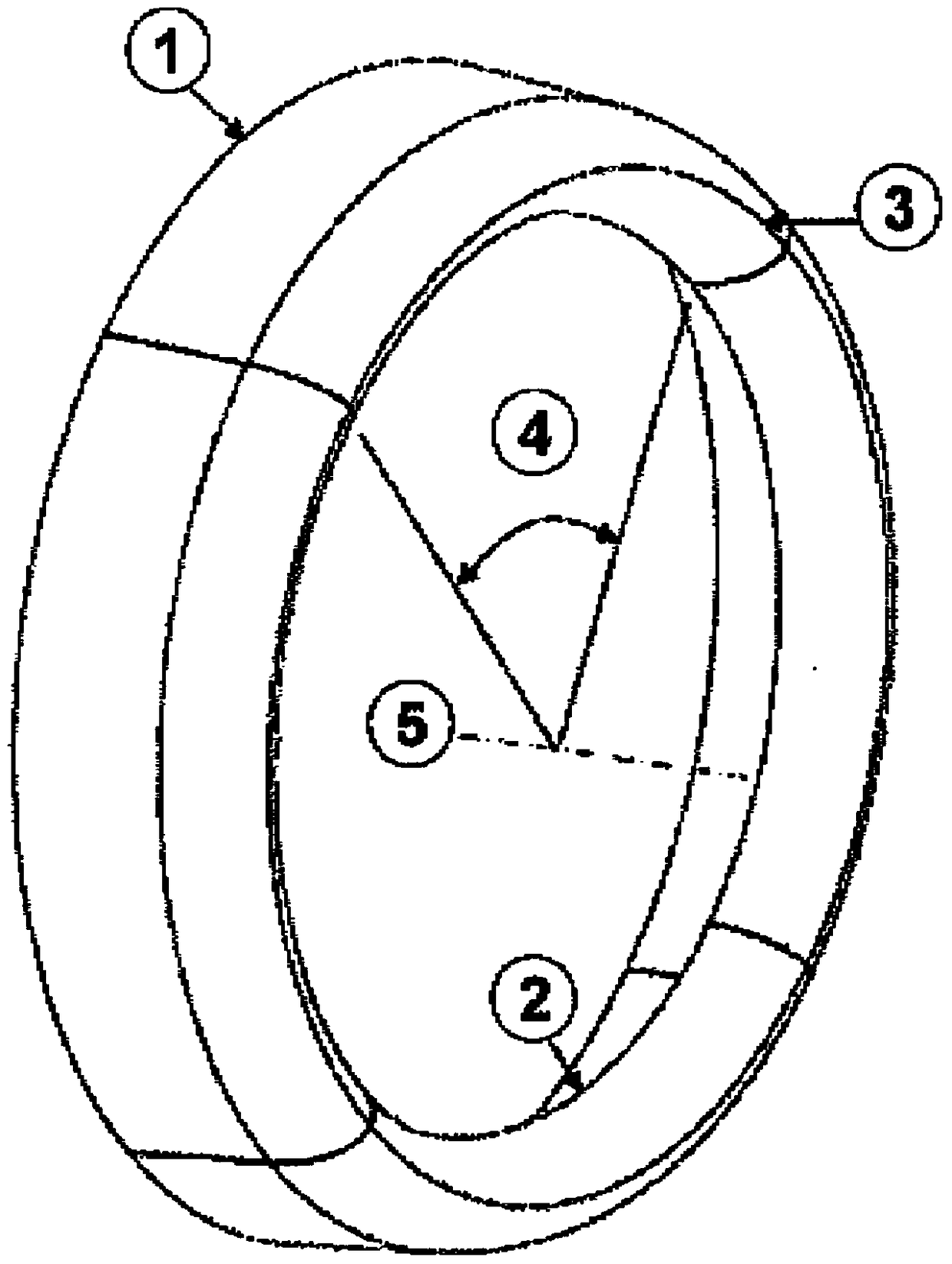
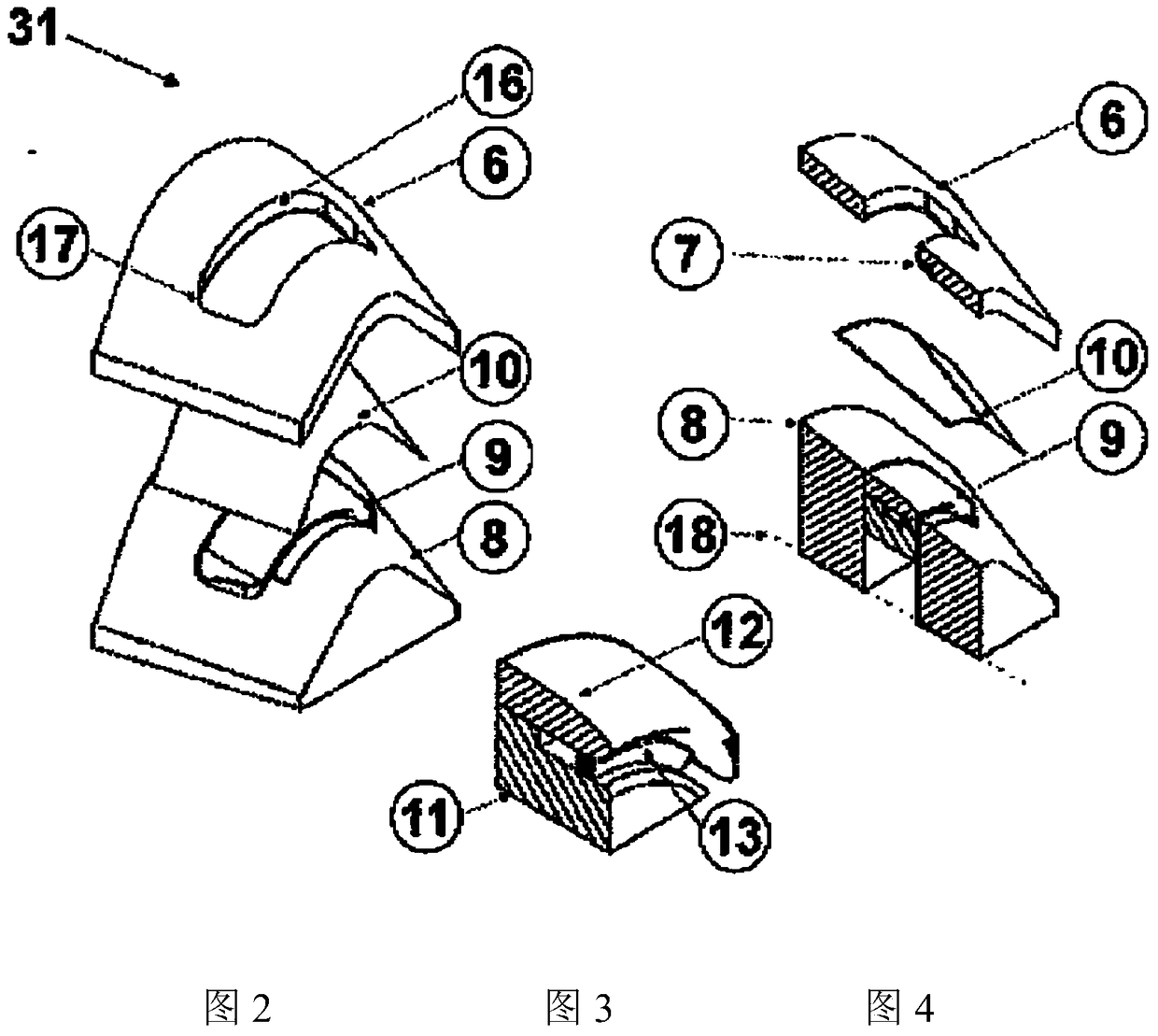
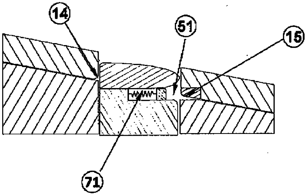
[0136] With reference to the attached drawings and first to the Figures 1 to 5F , shows a device generally indicated by reference numeral 31 for forming a sector of lip skin of an aircraft nacelle. The device 31 has a die plate 6 with a cast or machined surface supported by a further cast or machined structure, not shown, which transmits the force from the die plate 6 to the pressure system. The surface of the die plate 6 is made of a linearly extending conical section on each side. The surface of the die plate is designed to ensure uniform drawing on the surface of the punch 12 while providing sufficient clearance for the inner surface of the secondary drawing by utilizing the secondary drawing annular sector 7 . The cutout 16 in the center of the die plate 6 is shaped to match the shape of the punch 12 with a small clearance for the material blank thickness. The corners of the cutouts 16 are rounded 17 to ensure sufficient material flow to minimize buckling. The inner pe...


PUM


Abstract

Means (21, 31) for forming a sector of an annular part, having means (6, 8, 28, 30, 34) for securely holding at least a part of a blank plate mounted thereon. Said holding means (6, 8, 28, 30, 34) are adapted to make accessible a part of the holding blank. Punches (12, 32) are provided having the entire profile formed with the sector of the annular part from the trailing edge (1) to the leading edge (3) and/or from the leading edge (3) to the inlet edge (2) Or part of the contour shape corresponding to the outer surface contour. Said means (21, 32) have cooperating forming means (15, 44) for forming the contour of the sector of the annular part from the leading edge (3) to the inlet edge (2). The holding means (6, 8, 28, 30, 34) are adapted to form a clamping boundary surrounding an accessible portion of the blank to be formed by a punch (12, 32).

Description

technical field [0001] The present invention relates to lip skin sectors and methods and apparatus for forming lip skin sectors. Background technique [0002] The lip skin is the mechanical component around the inlet opening of the aircraft nacelle. The nacelle generally has a thin, aerodynamically shaped metal skin covering the aircraft's jet engines. The lip skin is generally constructed of a single member or multiple sectors, and the main feature of the lip skin is a smooth outer trailing edge, which must be free of irregularities and discontinuities to reduce drag and Prevent turbulence from forming. The inboard inlet lip is usually shaped to attenuate noise from the engine and direct airflow into the engine by shielding fan noise, the leading edge or lip provides a smooth transition between the outboard trailing edge and the inboard inlet lip while creating a small frontal area to reduce resistance. [0003] The complex three-dimensional compound curved shape of the...

Claims


Application Information

Patent Timeline
IPC IPC(8): B21D53/92B21D25/02B21D25/04
CPCB21D25/02B21D25/04B21D53/92F02C7/04B64D29/00F05D2230/00B64F5/00B64D2033/0273B64D2033/0286E21B47/085B21D22/02
Inventor 迈克尔·拉德洛大卫·麦克拉肯
Owner ROHR INC
Why Eureka
Try Eureka