Granular fuel-adopted tea strip tidying machine
A technology of pellet fuel and strip machine, which is applied in the directions of fuel supply, combustion of solid fuel, combustion method, etc., can solve the problems of poor strip effect, low production cost and high power consumption.
- Summary
- Abstract
- Description
- Claims
- Application Information
AI Technical Summary
Problems solved by technology
Method used
Image

Examples
Embodiment 1
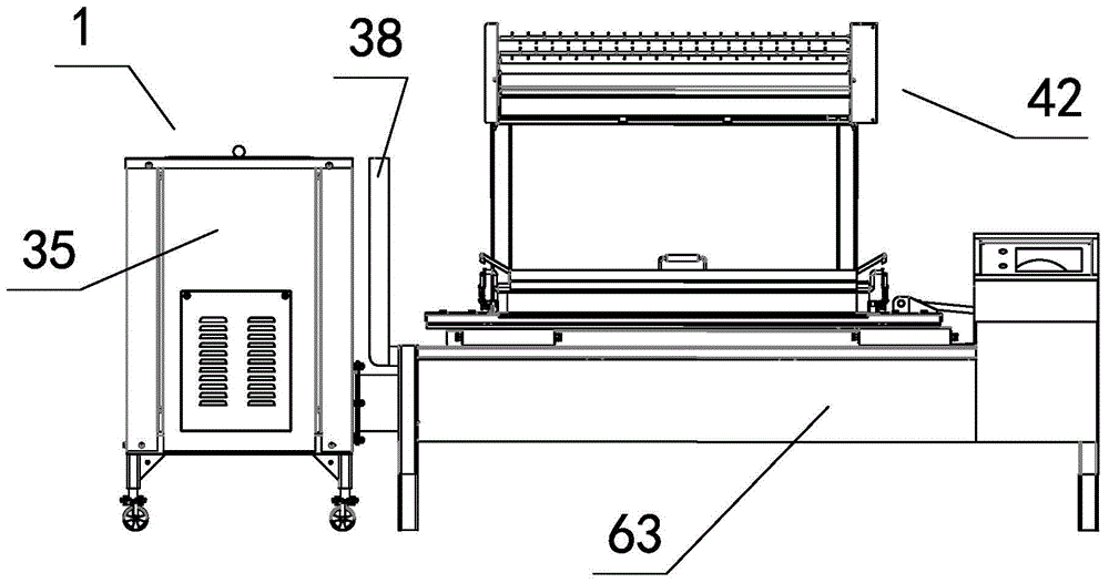
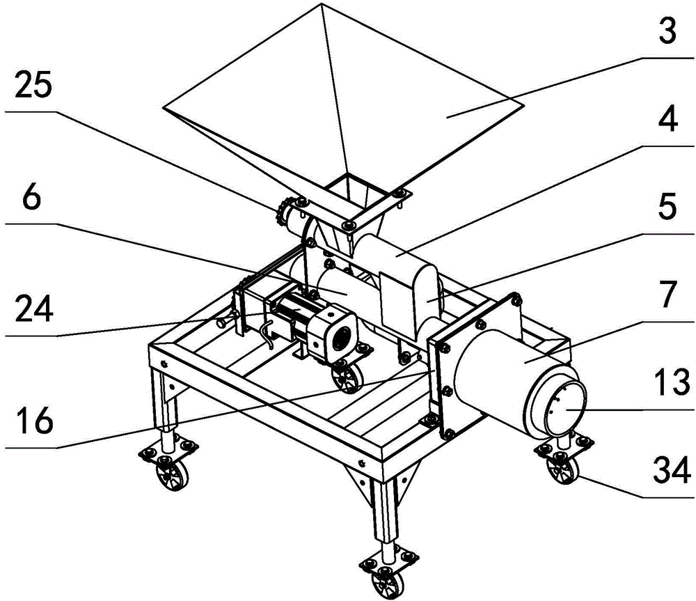
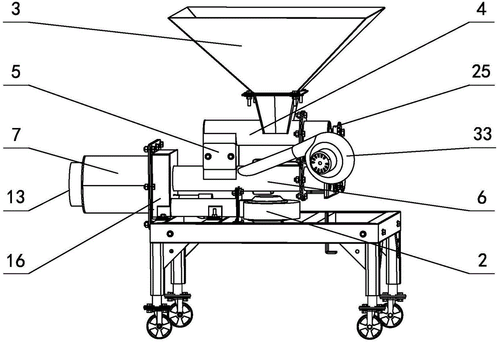
[0043] in such as figure 1 In the shown embodiment 1, a kind of granular fuel slitting machine includes a main body 63 and a swinging pot arranged on the main body, the groove cross section of the pot is U-shaped, and the U-shaped groove The opening width is 130 to 170 mm (155 mm in this embodiment), the depth of the U-shaped groove is 1.05 to 1.15 times (1.1 times in this embodiment) of the opening width groove, and the rear side of the main body is provided with a tea supply Material platform 42, the bottom of described pot 41 is also provided with heating chamber 40 (see Figure 19 ), the left side of the heating chamber is connected to the pellet fuel burner 1, and the right side of the heating chamber is connected to the smoke exhaust pipe 38 through 7 heating pipes 39 arranged between the pot and the heating chamber. sensor; the pellet fuel burner includes a housing 35, a feeding system, a burner and a main fan 2 (see Figure 2-Figure 6 ), the conveying system includes...
Embodiment 2
[0048] The uniform material auger of the pellet fuel burner in embodiment 2 is composed of the input section 18, the material uniform section 19 and the output section 20 driven by the same auger shaft, and the length of the uniform material section is less than the length of the input section and the output section. , the direction of rotation of the auger sheets of the input section and the output section is consistent, and the direction of rotation of the auger sheets of the uniform material section is opposite to that of the auger sheets of the input section and the output section; the auger shaft of the output section is fixed with a material lever 21 , the material lever is provided with a runner 22 that can rotate around the material lever, and the outer circumference of the runner extends with a material lever 23 that is inclined to the radial plane of the runner and its end is away from the material lever (see Figure 7 Figure 8 ), the center line in the length direc...
Embodiment 3
[0050] The air supply cavity of the particulate fuel burner in embodiment 3 is provided with a spiral spacer 26 (see Figure 10 ), the adjacent spiral partitions and the walls of the inner cylinder and the outer cylinder form a spiral air duct surrounding the inner cylinder. There are three spiral air ducts, and the air inlet end of the spiral air duct is connected to the air inlet box. The end of the duct is closed, and the air supply direction of the air supply holes is in the tangential direction of the inner tube circumference, and the distribution density of the air supply holes gradually increases from the air inlet end of the spiral air duct to the end of the spiral air duct; The inner wall is provided with a raised spiral rib 27, the position of the spiral rib is corresponding to the spiral spacer, the height of the protrusion of the spiral rib is 5 to 10 mm (8 mm in this embodiment), and the rest Same as embodiment 1 or embodiment 2.
PUM
 Abstract
Description
Claims
Application Information
 - R&D Engineer
- R&D Manager
- IP Professional
- Industry Leading Data Capabilities
- Powerful AI technology
- Patent DNA Extraction
Browse by: Latest US Patents, China's latest patents, Technical Efficacy Thesaurus, Application Domain, Technology Topic.
© 2024 PatSnap. All rights reserved.Legal|Privacy policy|Modern Slavery Act Transparency Statement|Sitemap