Electric leg carrying rack

An electric, leg-supporting technology, applied in medical science, hospital beds, hospital equipment, etc., can solve the problems of human resource waste, knee joint fatigue, knee joint emptying, etc., and achieve the effect of simple and convenient adjustment, simple structure, and reliable support.

Inactive Publication Date: 2015-11-25
UNIV OF SHANGHAI FOR SCI & TECH
View PDF6 Cites 15 Cited by
  • Summary
  • Abstract
  • Description
  • Claims
  • Application Information

AI Technical Summary

Problems solved by technology

If the patient's limb is raised by the hospital bed, firstly, it takes a long time to prepare for disinfection, and secondly, the hospital bed occupies a large area; if the patient's limb is raised by manpower, it will not only increase the cost of medical care, cause a waste of human resources, but also easily cause the patient's illness. Uncomfortable, long-term elevation makes both doctors and patients feel tired
[0003] The commonly used leg support or tripod support in the market has only one support position, and almost all of them are manually operated. When performing surgery on the calf or foot, the one-line theorem is determined by two points. Even if two

Method used


Image

  • Electric leg carrying rack
  • Electric leg carrying rack
  • Electric leg carrying rack

Examples


Embodiment Construction

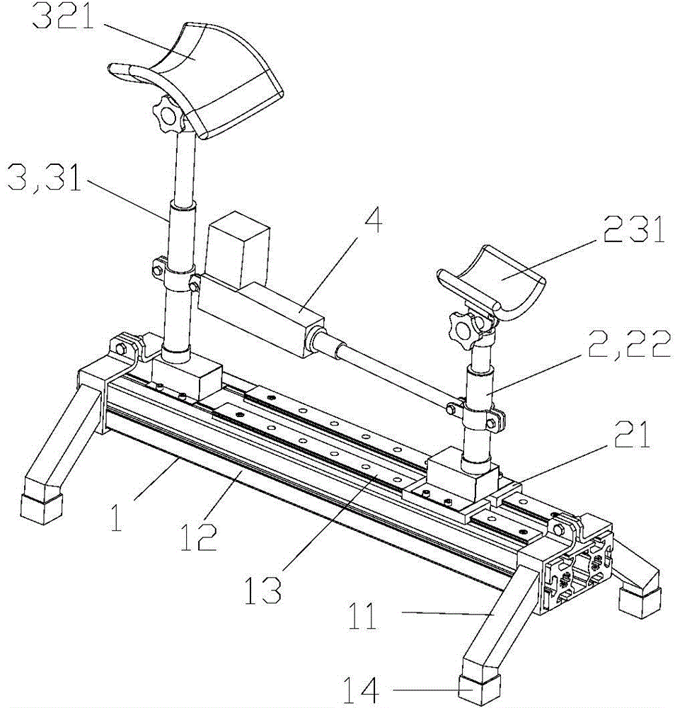
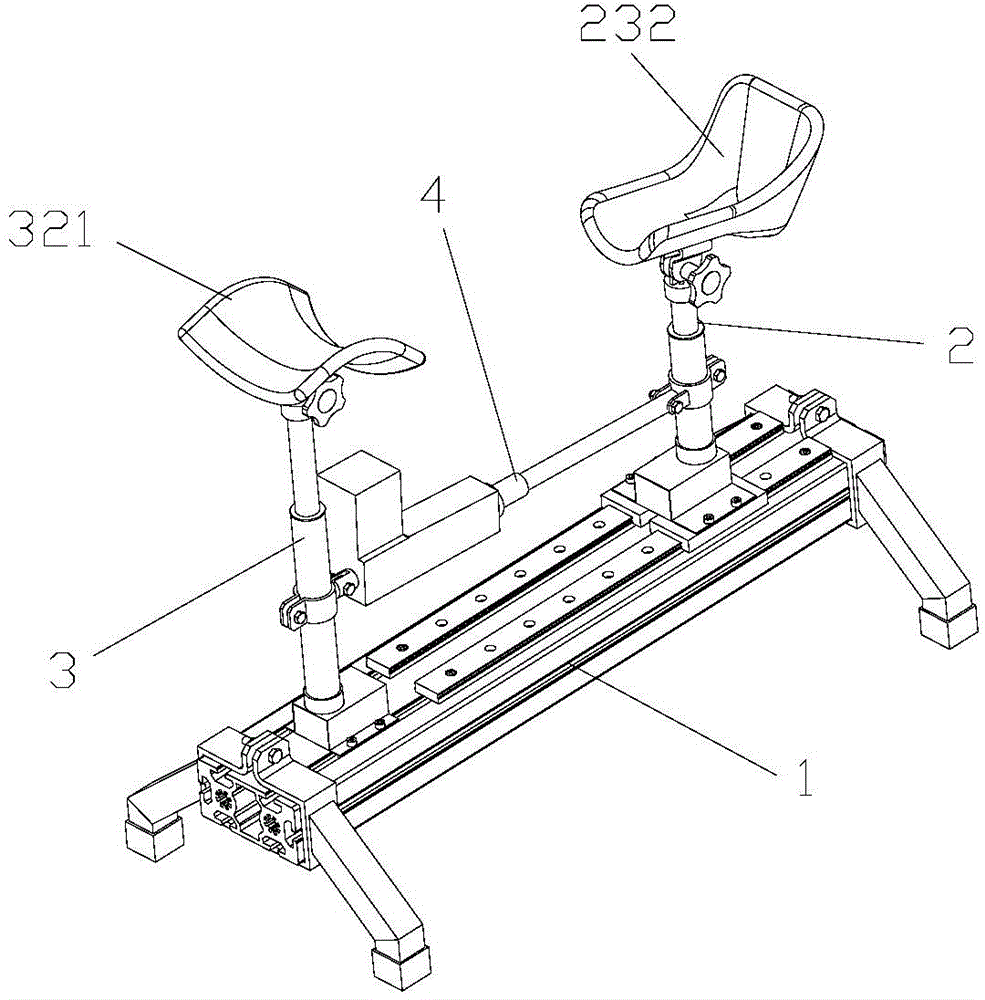
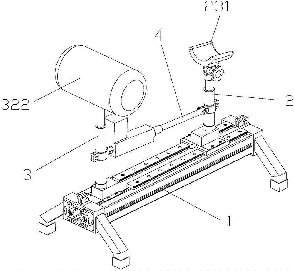
[0025] see figure 1 , with reference to figure 2 , image 3 , Figure 4 , The electric leg support of the present invention includes a base 1 , a foot support 2 , a knee support 3 and an electric push rod 4 .

[0026] The base 1 includes a seat leg 11, a beam 12 erected on the seat leg and a guide rail 13 installed on the beam; the seat leg 11 is arranged at both ends of the beam and fixed on the beam by locking bolts, and a non-slip sleeve is set on the bottom of the seat leg 14 or the universal wheel (not shown) with self-locking is installed, and guide rail 13 is installed on the crossbeam, and guiderail length is shorter than crossbeam, but guiderail length is longer than electric push rod stroke.

[0027] The foot support frame 2 is installed on the guide rail 13 of the base beam 12 and can move forward and backward along the guide rail; it includes a slider 21, a first electric column 22 and foot rests 231, 232, and the slider is installed on the beam of the seat leg...


PUM


Abstract

An electric leg carrying rack comprises a pedestal, a foot part supporting rack, a knee part supporting rack and an electric pushing rod, wherein the pedestal is formed by seat legs, a transverse beam bridged on the seat legs and a guide rail installed on the transverse beam; the knee supporting rack is arranged on the guide rail on the pedestal transverse beam via a slide block and can move front and back along the guide rail; the knee supporting rack is fixed on the transverse beam of the pedestal; and the electric pushing rod is connected between the foot part supporting rack and the knee part supporting rack. A foot bearer is arranged on the foot part supporting rack; the foot bearer can be an arc-shaped or an ankle foot orthotics; a knee bearer is mounted on the knee part supporting rack; and the knee bearer can be in a saddle shape or a cylindrical shape. The electric leg carrying rack is simply structured and easy to machine; supporting height and supporting positions of the patient knees and legs can be adjusted; firm supporting can be achieved; the supporting height and positions can be simply and conveniently adjusted; the user can adjust and control without help of other people; during the use, the lower limbs of the user are comfortably and naturally placed; disinfection and medicine exchange can be facilitated for the medical workers; the electric leg carrying rack can be easily cleaned after the use; and the user can also lift up the foot parts after long time sitting.

Description

technical field [0001] The invention relates to daily necessities, in particular to an electric leg support. Background technique [0002] When pathological changes occur in the patient's feet or lower limbs, such as fractures, etc., when disinfection, washing, dressing change, and bandaging are required, the affected limb needs to be raised for the convenience of hospital medical staff for medical care. If the patient's limb is raised by the hospital bed, firstly, it takes a long time to prepare for disinfection, and secondly, the hospital bed occupies a large area; if the patient's limb is raised by manpower, it will not only increase the cost of medical care, cause a waste of human resources, but also easily cause the patient's illness. Uncomfortable, long-term elevation makes both doctors and patients feel tired. [0003] The commonly used leg support or tripod support in the market has only one support position, and almost all of them are manually operated. When perfor...

Claims


Application Information

Patent Timeline
IPC IPC(8): A61G7/075
Inventor 张宇玲赵展喻洪流
Owner UNIV OF SHANGHAI FOR SCI & TECH
Why Eureka
Try Eureka