Cutting device for aerated bricks

A cutting device and a technology for aerated bricks, applied in the field of aerated brick manufacturing, can solve the problems of unqualified product quality, low production efficiency of cutting machines, adhesion and the like

Inactive Publication Date: 2015-11-25
重庆市泰日建材有限公司
View PDF6 Cites 2 Cited by
  • Summary
  • Abstract
  • Description
  • Claims
  • Application Information

AI Technical Summary

Problems solved by technology

[0005] The object of the present invention is to provide a cutting device for aerated bricks to solve the problem that the existing aerated bricks cutting machine has low production efficiency, and in the case of too short curing time of aerated bricks, it is easy to cause adhesion phenomenon, resulting in product The problem of unqualified quality

Method used


Image

  • Cutting device for aerated bricks
  • Cutting device for aerated bricks
  • Cutting device for aerated bricks

Examples


Embodiment 1

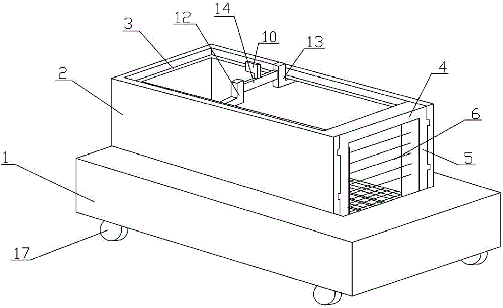
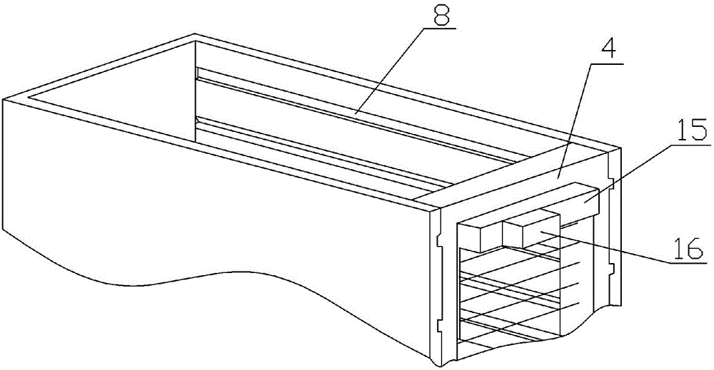
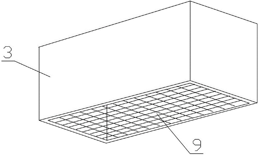
[0018] Embodiment 1 is basically as attached figure 1 , figure 2 Shown: a cutting device for aerated bricks, including a machine base 1, a transverse cutting frame 2 and a longitudinal cutting frame 3, the transverse cutting frame 2 and the longitudinal cutting frame 3 are arranged above the machine base 1, the transverse cutting frame 2 and the The vertical cutting frame 3 is a hollow cubic frame body, the horizontal cutting frame 2 is sleeved outside the vertical cutting frame 3, the horizontal cutting frame 2 is provided with a door frame-shaped mobile frame 4, and the two sides of the door frame-shaped mobile frame 4 are respectively provided with Columns 5, the first cutting steel wire group 6 is arranged between the columns 5, the first cutting steel wire group 6 includes several steel wires evenly distributed between the columns 5, the outer sides of the columns 5 on both sides of the door frame-shaped mobile frame 4 Be provided with slide block 7, be provided with ch...

Embodiment 2

[0022] Such as Figure 4 As shown, the structure and principle of this embodiment are basically the same as that of Embodiment 1, and the difference is that the uprights 5 on both sides of the doorframe-shaped mobile frame 4 are provided with pull rods 18 that pass through the transverse cutting frame 2, and the transverse cutting frame 2 There is a receiving groove 19 for accommodating the pull rod 18, the pull rod 18 is connected to a power device such as a cylinder, and the setting of the pull rod 18 can be used as the force point for the cylinder to pull / promote the door frame-shaped mobile frame 4, thereby driving the door frame-shaped mobile frame 4. The first cutting wire group 6 cuts the aerated brick. And pull rod 18 can be installed a plurality of along the vertical direction of column 5, and each pull rod 18 is all connected with cylinder, and so just can guarantee that the pulling force of cylinder to door frame shape mobile frame 4 is comparatively even in the cut...


PUM


Abstract

The invention discloses a cutting device for aerated bricks. The cutting device comprises a machine base, a transverse cutting frame and a vertical cutting frame. The transverse cutting frame and the vertical cutting frame are arranged above the machine base and are each a hollow cuboid frame. The vertical cutting frame is sleeved with the transverse cutting frame. A door-frame-shaped mobile rack is arranged on the transverse cutting frame. Stand columns are arranged on the two sides of the door-frame-shaped mobile rack. A first cutting steel wire set is arranged between the stand columns. Sliding blocks are arranged on the outer side faces of the stand columns on the two sides of the door-frame-shaped mobile frame. The transverse cutting frame is provided with sliding grooves where the sliding blocks are installed. A second cutting steel wire set arranged vertically and transversely is arranged on the bottom face of the vertical cutting frame. The problems that an existing aerated brick cutting machine is low in production efficiency, and because adhesion is likely to occur when the aerated brick maintenance time is too short, products are not qualified are solved.

Description

technical field [0001] The invention relates to the technical field of manufacturing aerated bricks, in particular to a cutting device for aerated bricks. Background technique [0002] Aerated brick is the abbreviation of "autoclaved aerated concrete block". It is a light-weight thermal insulation material containing a large number of closed pores. (lime, cement) as the main raw material, mixed with gas-generating agent (aluminum powder), stirred by adding water, the pores are formed by chemical reaction, and the porous silicate is made by casting molding, pre-curing cutting, autoclaving curing and other processes products. [0003] In the existing technology, the production and cutting process of aerated bricks are: 1) preparation of raw materials; 2) batching, mixing and pouring of raw materials; 3) constant temperature curing of raw materials to form embryo bodies; 4) embryo bodies Cutting and dividing into semi-finished products; 5) Finally, autoclaving and forming the...

Claims


Application Information

Patent Timeline
Patent Type & Authority Applications(China)
IPC IPC(8): B28B11/14
CPCB28B11/145
Inventor 林建涛
Owner 重庆市泰日建材有限公司
Why Eureka
Try Eureka