Sludge energy-saving drying unit and sludge energy-saving drying method

A sludge drying and sludge technology, applied in the direction of sludge treatment through temperature control, dehydration/drying/thickened sludge treatment, etc., can solve the problems of reducing the use of fresh steam, low evaporation water vapor temperature, unfavorable recovery, etc., to achieve Reduce raw steam consumption, reduce operating load, and achieve remarkable energy-saving effects

Inactive Publication Date: 2015-11-25
ACAD OF ENVIRONMENTAL PLANNING & DESIGN GRP CO LTD NANJING UNIV
View PDF13 Cites 1 Cited by
  • Summary
  • Abstract
  • Description
  • Claims
  • Application Information

AI Technical Summary

Problems solved by technology

[0006] Aiming at the technical problems of low evaporation water vapor temperature, low pressure, low grade, and unfavorable recovery, the present invention provides a sludge energy-saving drying device and a sludge energy-saving drying method. Through the present invention, the use of fresh steam in the sludge drying process can be greatly reduced It has a significant effect on protecting the environment, saving energy and reducing consumption, and promoting the sustainable development of the national economy and ecological environment. It has great social significance and is in line with relevant national industrial policies.

Method used


Image

  • Sludge energy-saving drying unit and sludge energy-saving drying method
  • Sludge energy-saving drying unit and sludge energy-saving drying method

Examples


Embodiment 1

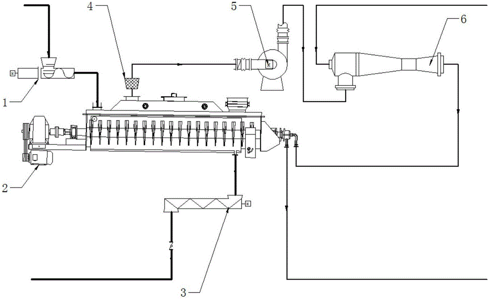
[0018] Such as figure 1 As shown, a sludge energy-saving drying treatment device in this embodiment includes a feeder 1, a sludge dryer 2 (the sludge dryer is a paddle dryer), a conveyor 3, a filter and dust removal device 4, a compressor 5 (the compressor is a centrifugal steam compressor), a pressurized mixer 6 (the pressurized mixer is a steam jet heat pump). Wherein the feeder is connected with the feed inlet above the paddle dryer; the outlet below the paddle dryer is connected with the conveyor; The air outlet of the dust removal device is connected with the inlet of the centrifugal steam compressor; the outlet of the centrifugal steam compressor is connected with the inlet of the steam jet heat pump; the outlet of the steam jet heat pump is connected with the inlet of the paddle dryer.

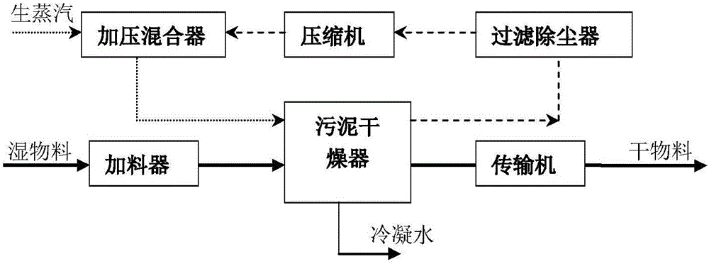
[0019] Such as figure 2 As shown, a sludge energy-saving drying treatment method includes the following steps: transporting the wet sludge to a paddle dryer through a feeder for dehy...

Embodiment 2

[0022] Such as figure 1 As shown, a sludge energy-saving drying treatment device in this embodiment includes a feeder 1, a sludge dryer 2 (the sludge dryer is a paddle dryer), a conveyor 3, a filter and dust removal device 4, a compressor 5 (the compressor is a Roots-type steam compressor), and the pressurized mixer 6 (the pressurized mixer is a steam jet heat pump). Wherein the feeder is connected with the feed inlet above the paddle dryer; the outlet below the paddle dryer is connected with the conveyor; The air outlet of the dust removal device is connected to the inlet of the Roots-type steam compressor; the outlet of the Roots-type steam compressor is connected to the inlet of the steam jet heat pump; the outlet of the steam jet heat pump is connected to the inlet of the paddle dryer.

[0023] A sludge energy-saving drying treatment method, comprising the following steps: transporting the wet sludge to a paddle dryer through a feeder for dehydration and drying treatment,...

Embodiment 3

[0026] Such as figure 1 As shown, a sludge energy-saving drying treatment device in this embodiment includes a feeder 1, a sludge dryer 2 (the sludge dryer is a vacuum disc dryer), a conveyor 3, a filter and dust removal device 4, a compressor 5 (the compressor is a centrifugal steam compressor), a pressurized mixer 6 (the pressurized mixer is a steam jet heat pump). Wherein the feeder is connected with the feed port above the vacuum disc dryer; the discharge port below the vacuum disc dryer is connected with the conveyor; The air outlet of the dust removal device is connected with the inlet of the centrifugal steam compressor; the outlet of the centrifugal steam compressor is connected with the inlet of the steam jet heat pump; the outlet of the steam jet heat pump is connected with the inlet of the vacuum disc dryer.

[0027] An energy-saving drying treatment method for sludge, comprising the following steps: transporting wet sludge to a vacuum tray dryer through a feeder f...


PUM


Abstract

The invention discloses a sludge energy-saving drying unit and a sludge energy-saving drying method, belonging to the field of energy-saving drying. The unit comprises a feeder (1), a sludge dryer (2), a conveyer (3), a filtering dust remover (4), a compressor (5) and a pressure mixer (6), wherein the feeder (1) is connected with an upper feed port of the sludge dryer (2); a lower discharge port of the sludge dryer (2) is connected with the conveyer (3); an upper exhaust port of the sludge dryer (2) is connected with a gas inlet of the filtering dust remover (4); a gas outlet of the filtering dust remover (4) is connected with an inlet of the compressor (5); an outlet of the compressor (5) is connected with an inlet of the pressure mixer (6); and an outlet of the pressure mixer (6) is connected with an inlet of the sludge dryer (2). The unit and method can greatly reduce the steam consumption in the steam heat drying process, have obvious effects on environment protection, energy saving and emission reduction, and have significant social and economic values.

Description

technical field [0001] The invention relates to an energy-saving drying device and method, in particular to an energy-saving drying device for sludge and an energy-saving drying method for sludge. Background technique [0002] As the energy supply situation becomes increasingly tense, energy prices rise further, production costs of enterprises increase, and competition pressure increases. According to literature reports, the energy consumption of the drying process in my country accounts for 10% of the energy consumption of the entire processing process, the heat energy consumption of veneer drying in plywood production accounts for 75% of the total energy consumption, and the energy consumption of wood drying accounts for 40% of the total energy consumption. % to 70%, the traditional hot air drying of sludge has low efficiency, and the heat consumption of 1kg of water needs to be evaporated to 4000~6000kJ. In order to better fulfill the purpose of national energy conservati...

Claims


Application Information

Patent Timeline
Patent Type & Authority Applications(China)
IPC IPC(8): C02F11/12C02F11/18
Inventor 李明陆朝阳樊健胡昌旭费正连姚琪
Owner ACAD OF ENVIRONMENTAL PLANNING & DESIGN GRP CO LTD NANJING UNIV
Why Eureka
Try Eureka