Method and apparatus for detecting soot and ash loading of a particle filter

A particle filter and smoke load technology, which is applied in the direction of exhaust device, muffler device, exhaust treatment device, etc., can solve the problem that the absolute pressure difference cannot be realized, so as to improve the quality of diagnosis, suppress signal fluctuations, improve The effect of accuracy

Active Publication Date: 2015-11-25
ROBERT BOSCH GMBH
View PDF6 Cites 20 Cited by
  • Summary
  • Abstract
  • Description
  • Claims
  • Application Information

AI Technical Summary

Problems solved by technology

Therefore, a direct correlation of absolute differential pressure...

Method used


Image

  • Method and apparatus for detecting soot and ash loading of a particle filter
  • Method and apparatus for detecting soot and ash loading of a particle filter
  • Method and apparatus for detecting soot and ash loading of a particle filter

Examples


Embodiment Construction

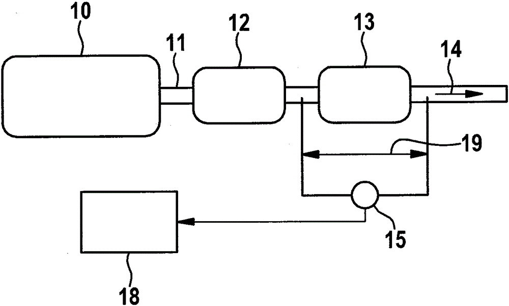
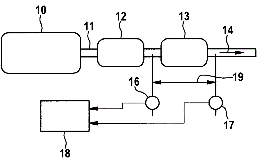
[0033] figure 1 The technical field in which the method according to the invention can be applied is schematically shown. An internal combustion engine 10 is shown as an example, which is embodied as a gasoline motor, wherein the exhaust gas of the internal combustion engine is conducted via an exhaust gas line 11 in which an exhaust gas cleaning device is arranged, which in the example shown is implemented in multiple stages . In the flow direction of the exhaust gas (exhaust gas flow 14 ), in the example shown there is firstly a catalytic converter 12 , which can be designed as a three-way catalytic converter, after which a particle filter 13 is arranged. Furthermore, exhaust gas sensors or other sensors, which of course are not shown in this schematic diagram, are usually arranged in the exhaust gas line 11 , the signals of which are fed to a motor control system (Electronic Control Unit ECU).

[0034] In order to diagnose the soot and ash load of the particle filter 13, ...


PUM


Abstract

The invention relates to a method for the detection of a soot and ash loading of a particulate filter as a component of an exhaust gas cleaning system in the exhaust line of an internal combustion engine, wherein a differential pressure between the inlet and outlet of the particulate filter is measured for monitoring the particulate filter and this is evaluated in a diagnostic unit. The invention further relates to a device, in particular a diagnostic unit for carrying out the provided method. The invention is characterized in that for determining the soot and ash charge the time gradient of the measured differential pressure is set at the particle filter in correlation with an expected temporal gradient of a differential pressure of an intact and unloaded reference particulate filter and this correlation different temporal trend analysis is subjected. Compared to the prior art, the method has the advantage that, even at very low absolute pressure differences, as in gasoline direct injection engines is the case in particular when the internal combustion engine, a load diagnosis of the particulate filter and distinction between ash and soot loading can be made possible.

Description

technical field [0001] The invention relates to a method for detecting the soot and ash load of a particle filter as part of an exhaust gas cleaning system in the exhaust gas line of an internal combustion engine, wherein, for monitoring the particle filter, a measurement The pressure difference between the inlet and outlet of the particle filter is evaluated in a diagnostic unit. [0002] The invention also relates to a device, in particular a diagnostic unit, for carrying out the method according to the invention. Background technique [0003] Emission regulations, in particular in the United States and in Europe, set limit values ​​for particulate matter emissions and particle numbers or particle concentrations. In addition to the emission limit values, diagnostic limit values ​​are likewise specified, if these diagnostic limit values ​​are exceeded, a fault must be indicated. To this end, a diagnostic function is carried out in the vehicle, which monitors components an...

Claims


Application Information

Patent Timeline
IPC IPC(8): F01N11/00F01N3/035
CPCF01N3/023F01N9/002F01N11/002Y02T10/40
Inventor T.蔡因T.鲍曼连运捷
Owner ROBERT BOSCH GMBH
Why Eureka
Try Eureka