Synchronous belt positioning system

A positioning system and synchronous belt technology, applied in belts/chains/gears, mechanical equipment, transmission devices, etc., can solve the problems of difficult processing and manufacturing, difficult maintenance and replacement, and difficult replacement and maintenance, and achieve low maintenance and replacement costs and high precision. The effect of reducing requirements and saving time and effort in assembly

Active Publication Date: 2015-11-25
SHENYANG ZHONGTUO ROBOT EQUIP
View PDF5 Cites 1 Cited by
  • Summary
  • Abstract
  • Description
  • Claims
  • Application Information

AI Technical Summary

Problems solved by technology

[0002] The existing synchronous belt positioning system can be divided into two types: line contact positioning system and point contact positioning system according to the different contact forms of the positioning system. Among them, the line contact positioning system includes guide rails, sliders and auxiliary mechanisms. This mechanism exists Defects such as low speed, high noise, difficult replacement and maintenance, and high cost of maintenance; while the point-contact positioning system is rarely used in the prior art, its processing and manufacturing are difficult, easy to wear, difficult to maintain and replace, and the manufacturing cost is too high , the point contact positioning system mainly includes a V-shaped rolling transmission mechanism, that is, the slider is made into a V-shaped

Method used


Image

  • Synchronous belt positioning system
  • Synchronous belt positioning system
  • Synchronous belt positioning system

Examples


Embodiment Construction

[0041] Hereinafter, the present invention will be further described in detail through the drawings and embodiments. Through these descriptions, the characteristics and advantages of the present invention will become clearer.

[0042] The dedicated word "exemplary" here means "serving as an example, embodiment, or illustration." Any embodiment described herein as "exemplary" need not be construed as being superior or better than other embodiments. Although various aspects of the embodiments are shown in the drawings, unless otherwise noted, the drawings are not necessarily drawn to scale.

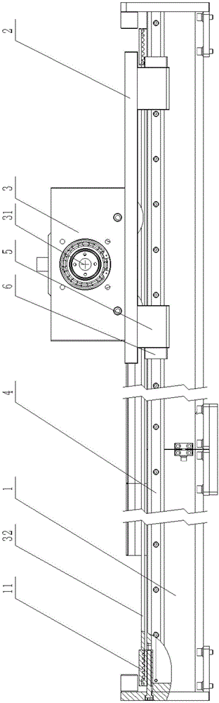
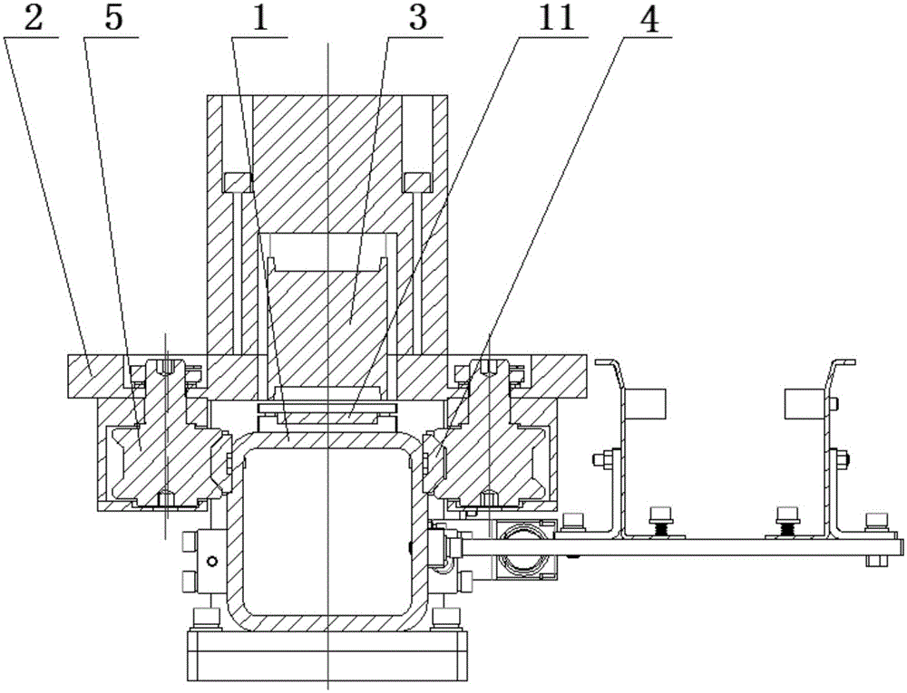
[0043] According to the timing belt positioning system provided by the present invention, such as figure 1 , figure 2 As shown in the figure, the system includes a main beam 1 and a sliding plate 2 arranged above the main beam 1. The sliding plate can slide reciprocatingly along the longitudinal direction of the main beam, thereby driving other components placed on the sliding plate to move tog...


PUM


Abstract

The invention discloses a synchronous belt positioning system. According to the system, a roller linear guide rail and a roller arc guide rail are combined. Limiting is carried out in a point contact manner. In other words, a belt transmission system is positioned through the guide rails and pulley mechanisms matched with the guide rails, and the pulley mechanisms are arranged into cam even eccentric wheel mechanisms so that the pretightening force between the pulley mechanisms and the guide rails can be adjusted. Furthermore, sliding rails are arranged on a main beam, the pulley mechanisms are arranged on a sliding plate, the sliding plate is further provided with a belt wheel drive assembly providing power for transmission of a synchronous belt, and synchronous belt tensioning mechanisms and lubricating assemblies are arranged to be matched with the belt wheel drive assembly.

Description

Technical field [0001] The invention relates to a belt drive positioning system, in particular to a synchronous belt positioning system. Background technique [0002] The existing timing belt positioning system can be divided into two types: line contact type and point contact type positioning system according to the different contact forms of the positioning system. Among them, the line contact type positioning system includes the guide rail, the sliding block and the auxiliary mechanism. This mechanism exists Low speed, high noise, difficult replacement and maintenance, high maintenance cost and other defects; while the point contact positioning system is rarely used in the existing technology, and its processing and manufacturing are difficult, easy to wear, difficult to repair and replace, and the manufacturing cost is too high , The point contact positioning system mainly includes a V-shaped rolling transmission mechanism, that is, the slider is made into a V-shaped. [0003]...

Claims


Application Information

Patent Timeline
Patent Type & Authority Applications(China)
IPC IPC(8): F16H7/18
CPCF16H7/18F16H2007/185
Inventor 杨树彬
Owner SHENYANG ZHONGTUO ROBOT EQUIP
Why Eureka
Try Eureka