Automatic feeding mechanism

A technology of automatic feeding and feeding mechanism, which is applied in the microwave field, can solve the problems of high cost, uneven spatial distribution, and many operating equipment, so as to reduce the space for equipment operation, high degree of equipment automation, and small equipment operation space Effect

Active Publication Date: 2015-11-25
NANJING SANLE MICROWAVE TECH DEV
View PDF10 Cites 2 Cited by
  • Summary
  • Abstract
  • Description
  • Claims
  • Application Information

AI Technical Summary

Problems solved by technology

However, the structure of the retractable belt conveyor is too complex and inconvenient to install; there are many operating equipment and the cost is too high
[0005] With the application of microwave energy to the medical waste treatment industry, if the material conveying system is not efficient and t

Method used


Image

  • Automatic feeding mechanism
  • Automatic feeding mechanism
  • Automatic feeding mechanism

Examples


Embodiment Construction

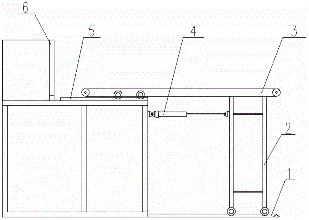
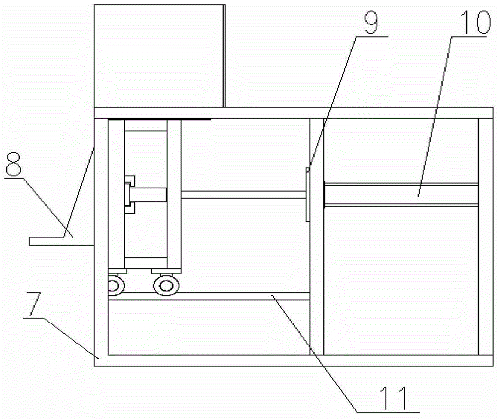
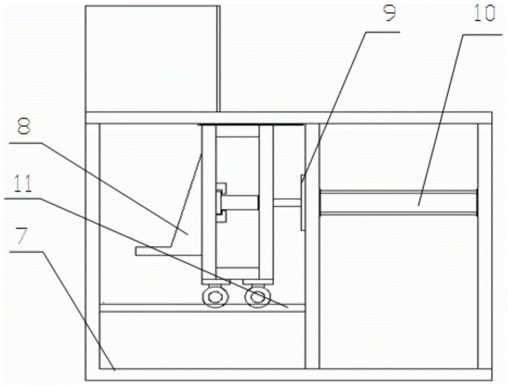
[0014] The automatic feeding mechanism of the present invention is mainly composed of two parts: a belt line feeding mechanism and a cylinder feeding mechanism.

[0015] Belt line feeding mechanism

[0016] Such as figure 1 As shown, the belt line feeding mechanism includes a conveyor belt 3, a movable machine leg 2, a first group of guide rails 1, a first cylinder 4 and a second group of guide rails 5;

[0017] The conveyor belt 3 is equipped with at least two rollers on both sides near the upper end of the bin door 6, the rollers are placed on the second group of guide rails 5, and the second group of guide rails 5 are arranged on the table top of the cylinder feeding mechanism frame 7, The other end of the conveyor belt 3 is fixedly placed on the mobile machine leg 2; at least two rollers are installed at the lower end of the mobile machine leg 2, and the mobile machine leg 2 is placed on the first group of guide rails 1 by the rollers on the machine leg.

[0018] The mob...


PUM


Abstract

The invention provides an automatic feeding mechanism, which comprises a belt line material conveying mechanism and an air cylinder feeding mechanism, wherein the belt line material conveying mechanism comprises a conveying belt, movable machine legs, a first group of guide rails, a first air cylinder and a second group of guide rails; at least two rolling wheels are arranged at two sides of one end, near an upper cabin door of a material cabin, of the conveying belt; the rolling wheels are put onto the second group of guide rails; the lower ends of the movable machine legs are provided with at least two rolling wheels; the movable machine legs are put on the first group of guide rails through the rolling wheels arranged on the machine legs; the air cylinder feeding mechanism consists of a material cabin, a second air cylinder, a machine frame, a furnace door combination and a third group of guide rails; the material cabin is arranged on a table top of the machine frame; the material cabin is not provided with a bottom; a feeding opening matched with the bottom of the material cabin is formed in the table top; the second air cylinder is horizontally arranged on an air cylinder installing post of the machine frame; and the end part of a piston rod of the second air cylinder is arranged on a door framework. The automatic feeding mechanism has the advantages that the structure is simple; the operation space of equipment is small; the automation degree is high; the production efficiency is improved; and the production cost is reduced.

Description

technical field [0001] The invention belongs to the field of microwave technology, and in particular relates to an automatic feeding mechanism matched with microwave heating equipment. Background technique [0002] At present, in order to speed up the delivery of materials, the supporting feeding system on domestic microwave heating equipment often ignores the efficiency and effect of material delivery for some special materials like medical waste. [0003] For example, medical waste is conveyed using a traditional conveyor belt structure. The traditional conveyor belt structure is composed of a frame, a main shaft, idler rollers, a conveyor belt, etc. The motor drives the main shaft, the main shaft drives the conveyor belt, and the conveyor belt carries the materials to the external door. The external door monitors the material and opens it. The inner conveyor belt continues to move forward structurally, the outer door is closed, and when the material is close to the inner...

Claims


Application Information

Patent Timeline
IPC IPC(8): F23G7/00F23K5/00
CPCF23G7/00F23K5/00
Inventor 李斌姚腾程跃周佳扬
Owner NANJING SANLE MICROWAVE TECH DEV
Why Eureka
Try Eureka