Photoelectric conversion module, temperature compensation method for photoelectric conversion module, and distributed light sensing system

A photoelectric conversion module, temperature compensation technology, applied in thermometers, thermometer testing/calibration, thermometers with physical/chemical changes, etc., can solve problems such as low concentration, affecting equipment use and reliability, and system instability, etc. Achieve the effect of improving stability, avoiding potential instability, and facilitating integrated management

Inactive Publication Date: 2015-11-25
深圳市迅捷光通科技有限公司
View PDF5 Cites 6 Cited by
  • Summary
  • Abstract
  • Description
  • Claims
  • Application Information

AI Technical Summary

Problems solved by technology

figure 1 The photoelectric receiving subsystem 104 is actually composed of two photoelectric conversion units. The photoelectric conversion units are generally scattered in various parts of the system, and the concentration is not high. There are often system instability caused by temperature changes, high and low temperatures, and device aging. problems that affect the use and reliability of the device

Method used


Image

  • Photoelectric conversion module, temperature compensation method for photoelectric conversion module, and distributed light sensing system
  • Photoelectric conversion module, temperature compensation method for photoelectric conversion module, and distributed light sensing system
  • Photoelectric conversion module, temperature compensation method for photoelectric conversion module, and distributed light sensing system

Examples


Embodiment Construction

[0028] In order to have a clearer understanding of the technical features, purposes and effects of the present invention, the specific implementation manners of the present invention will now be described in detail with reference to the accompanying drawings.

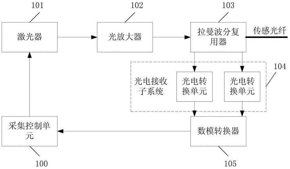
[0029] Firstly, the function of the photoelectric conversion module of the present invention is introduced by taking the distributed optical fiber temperature measurement system as an example. Although the application of the photoelectric conversion module is not limited to the distributed optical fiber temperature measurement system, it is still applicable to many other types of distributed optical fiber sensing systems. , but as a typical application of this subsystem, the application of this system in a distributed optical fiber temperature measurement system will be taken as an example below to illustrate. refer to figure 1 , the working process is as follows: when the acquisition starts, the acquisition control uni...


PUM


Abstract

The invention provides a photoelectric conversion module, a temperature compensation method for the photoelectric conversion module, and a distributed light sensing system. The module comprises a control sub-module and two signal processing sub-modules. Each signal processing sub-module includes an avalanche photodiode. The control sub-module is used for compensating the working state point of the avalanche photodiode so as to enable the avalanche photodiode to run at an optimal working point, based on the mapping relationship between the current temperature detected in real time and the optimal working point of the avalanche photodiode. In this way, in different temperature environments, the module is kept to run at the optimal working point. Even in conditions wherein the ambient temperature rapidly changes or is extremely high/low, the module is ensured to run stably for a long time. Furthermore, by means of a trans-impedance amplifier and a signal conditioning, amplifying and filtering circuit, the local noise is reduced, and the signal-to-noise ratio and the stability of the system are improved. Moreover, the module is enclosed in a closed housing, so that the influence of the varying environment outside the housing on parts inside the housing is lowered. Therefore, the system stability is improved.

Description

technical field [0001] The invention relates to the field of distributed optical fiber sensing, in particular to a photoelectric conversion module, a parameter setting method thereof, and a distributed light sensing system. Background technique [0002] The distributed optical fiber temperature measurement sensor system is a temperature measurement system based on the OTDR principle with optical fiber as the sensing element. With its passive, intrinsically safe, quantitative temperature measurement, it is insensitive to electromagnetic interference and has a low false alarm rate. With the advantages of long service life and low maintenance cost, it is more and more widely used in fire alarm detection and temperature detection. In many practical applications, people have put forward higher and higher requirements for the performance of distributed optical fiber temperature measurement: the measurement distance is getting longer and the response time is getting faster, or the ...

Claims


Application Information

Patent Timeline
Patent Type & Authority Applications(China)
IPC IPC(8): G01K11/32G01K15/00G01K11/324
Inventor 郑华明陈建成
Owner 深圳市迅捷光通科技有限公司
Why Eureka
Try Eureka