Internal-pressure-cylinder pressure testing method and system

A pressure test, cylinder technology, applied in the direction of applying stable tension/pressure to test the strength of materials, measuring devices, instruments, etc., can solve the problems of high liquid temperature requirements, high vaporization pressure, low viscosity, etc., to simplify the test. System, fast pressure relief, simple operation effect

Inactive Publication Date: 2015-11-25
BEIJING INSTITUTE OF TECHNOLOGYGY
View PDF7 Cites 8 Cited by
  • Summary
  • Abstract
  • Description
  • Claims
  • Application Information

AI Technical Summary

Problems solved by technology

Traditional hydraulic tests generally use water as the transmission medium, and water has the characteristics of low viscosity, poor lubricity, strong conductivity, and high vaporization pressure, which makes hydraulic tests prone to leakage, hydraulic components easy to be worn and corroded, and poor cavitation resistance, etc. defects, and because the material properties of the composite material itself are greatly affected by temperature, the traditional hydraulic test requires higher liquid temperature
The general air pressure test has strict requirements and is very dangerous. The blasting force of air pressure is very strong, and the safety measures for the test site are very high. Before the test, 100% non-destructive testing must be carried out on the main gaps of the container.
Moreover, whether it is a pneumatic test or a hydraulic test, it can only be carried out on special test equipment. Because the pressure transmission medium in this type of test system is liquid or gas, the experimental equipment must have pipelines or components containing liquid or gas, and the test process In the test cylinder, it is necessary to seal the test cylinder by adding a head or a liner. Before the test, an airtight test must be carried out, which makes the structure of the test equipment complicated and the operation of the test process inconvenient. After the cylinder is broken during the test, the pressure transmission medium The test site is seriously polluted, and the protection of site personnel and equipment is difficult

Method used


Image

  • Internal-pressure-cylinder pressure testing method and system
  • Internal-pressure-cylinder pressure testing method and system
  • Internal-pressure-cylinder pressure testing method and system

Examples


Embodiment Construction

[0017] The present invention will be described in detail below with reference to the accompanying drawings and examples.

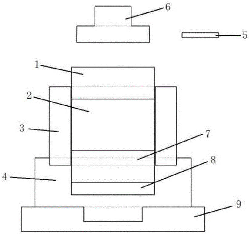
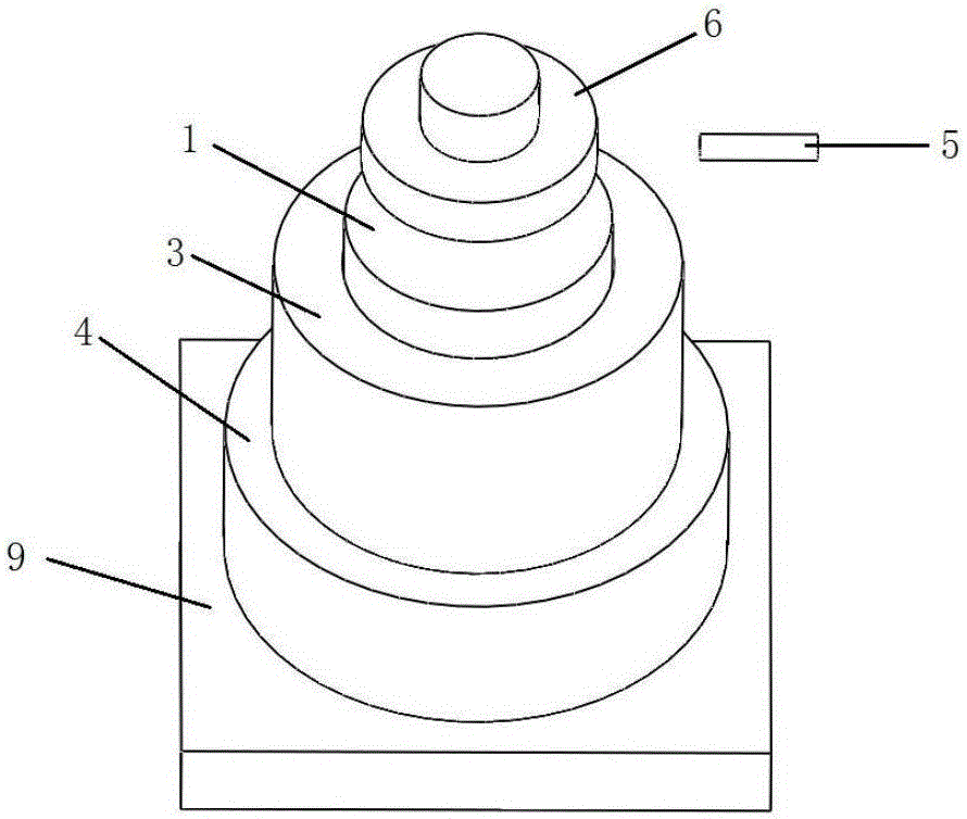
[0018] as attached figure 1 and 2 As shown, the present invention provides an internal pressure cylinder pressure test system, comprising a press 6, an upper pressure plate 1, a compression body 2, a lower pressure plate 7, a test cylinder 3, a base 4, a pressure sensor 8, a deformation measurement Component 5 and Workbench 9;

[0019] The compression body 2 is made of solid elastic material and has a cylindrical shape;

[0020] The upper surface of the base 4 is processed with two-stage stepped holes, the lower surface is processed with a cylindrical boss, and the stepped hole is coaxial with the central axis of the cylindrical boss;

[0021] A central positioning groove is processed on the upper surface of the workbench 9;

[0022] The cylindrical boss of the base 4 is fixedly connected with the central positioning groove of the workbench 9, the pres...


PUM


Abstract

The invention discloses an internal-pressure-cylinder pressure testing method and a system, and belongs to the technical field of examination equipment. According to the method, a solid elastic material is employed for replacing a conventional compression medium, and the solid elastic material is processed into a cylindrical compression body and is put into a test cylinder, the compression body generates radial expansion under the axial compression force and stresses the test cylinder, and an expected internal pressure and a loading process are obtained by controlling the loading speed of a press. If the test cylinder fails during an experiment, because the compression body is easily compressed, the pressure in the test cylinder rapidly decreases, and a large amount of energy is absorbed by the compression body. Therefore, the destroying capability of the residual energy to test on-site equipment and personnel is substantially reduced.

Description

technical field [0001] The invention relates to an internal pressure cylinder pressure test method and system for composite material pressure vessels, in particular to an internal pressure cylinder pressure test method and system based on a common press, and belongs to the technical field of inspection equipment. Background technique [0002] Internal pressure cylinders have a wide range of applications. At present, the main material used for internal pressure cylinders in China is steel, and the comprehensive performance of steel materials has certain limitations, which brings certain disadvantages to the manufacture of internal pressure cylinders. As a new type of material with strong designability, identity of material and structure, high specific strength and high specific stiffness, composite materials have many advantages when applied to internal pressure cylinders: (1) The pressure cylinder is light in weight, high in rigidity and strength; (2) Composite materials can...

Claims


Application Information

Patent Timeline
Patent Type & Authority Applications(China)
IPC IPC(8): G01N3/08G01N3/02
Inventor 皮爱国刘柳左腾田春雷黄风雷
Owner BEIJING INSTITUTE OF TECHNOLOGYGY
Why Eureka
Try Eureka