Chip wafer and manufacturing method thereof

A manufacturing method and wafer technology, which are applied in semiconductor/solid-state device manufacturing, electrical components, and electrical solid-state devices, etc., can solve the problems of inability to penetrate the interlayer dielectric layer and the size of the contact hole at the edge of the wafer, etc. Yield, the effect of avoiding short circuits

Active Publication Date: 2015-11-25
SEMICON MFG INT (SHANGHAI) CORP
View PDF6 Cites 3 Cited by
  • Summary
  • Abstract
  • Description
  • Claims
  • Application Information

AI Technical Summary

Problems solved by technology

[0004] The purpose of this application is to provide a chip wafer and its manufacturing method to solve the problem that the feature size

Method used


Image

  • Chip wafer and manufacturing method thereof
  • Chip wafer and manufacturing method thereof
  • Chip wafer and manufacturing method thereof

Examples


Example Embodiment

[0023] It should be noted that the embodiments in the application and the features in the embodiments can be combined with each other if there is no conflict. Hereinafter, the present application will be described in detail with reference to the drawings and in conjunction with the embodiments.

[0024] It should be noted that the terms used here are only for describing specific implementations, and are not intended to limit the exemplary implementations according to the present application. As used herein, unless the context clearly dictates otherwise, the singular form is also intended to include the plural form. In addition, it should also be understood that when “including” and / or “including” are used in this specification, it indicates There are features, steps, operations, devices, components, and / or combinations thereof.

[0025] For ease of description, spatially relative terms can be used here, such as "above", "above", "above the surface", "above", etc., to describe as s...


PUM


Abstract

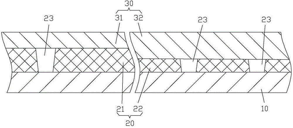
The application discloses a chip wafer and a manufacturing method thereof. The chip wafer comprises a substrate; an interlayer dielectric layer, disposed on the substrate, and provided with a plurality of contact holes which penetrate through the interlayer dielectric layer in a direction perpendicular to the substrate; a metal layer, disposed on the interlayer dielectric layer; and a plurality of connecting portions, being respectively located in the plurality of contact holes and connecting the metal layer and the substrate. The interlayer dielectric layer comprises a first region and a second region surrounding the first region, the contact holes are disposed in both the first region and the second region, and the thickness of the first region is greater than that of the second region. According to the application, as the thickness of the region, located at the edge of the chip wafer, of the interlayer dielectric layer is reduced, that is the second region is thinned, the contact holes can more easily penetrate through the interlayer dielectric layer, the problem that the contact holes cannot penetrate through the interlayer dielectric layer is avoided, the connecting portions in the contact holes can be ensured to reliably connect the metal layer and the substrate, and the yield of the edge part of the chip wafer is improved.

Description

Technical field [0001] This application relates to the field of integrated circuits, and more specifically, to a chip wafer and a manufacturing method thereof. Background technique [0002] In the existing technology, such as figure 1 As shown, a contact hole 23' is provided on the interlayer dielectric layer 20' of the chip wafer so as to make a connection part in the contact hole 23' to connect the substrate 10' and the metal on both sides of the interlayer dielectric layer 20' Floor 30'. [0003] In the prior art, etching methods are commonly used to make contact holes 23'. However, due to the limitation of hardware equipment, the etching rate of the edge of the chip wafer is relatively low, which directly causes the contact holes 23' located at the edge of the chip wafer to be damaged. The feature size becomes smaller. According to experimental statistics, the average diameter of the contact hole 23' in the center of the chip wafer is 73nm, but the average diameter of the con...

Claims


Application Information

Patent Timeline
IPC IPC(8): H01L23/528H01L21/768
Inventor 王志高
Owner SEMICON MFG INT (SHANGHAI) CORP
Why Eureka
Try Eureka