
Step-by-step locking device for plug of novel electric car connector

A technology for connector plugs and electric vehicles, which is applied to the parts, connections, coupling devices and other directions of connecting devices, can solve the problems of charging safety restricting rechargeable electric vehicles, complex structure of step-by-step locking devices, and difficulty in use. , to achieve the effect of eliminating hidden dangers of electricity consumption, easy production and maintenance, and easy operation

Active Publication Date: 2015-11-25
SHENZHEN BUSBAR SCI TECH DEV
View PDF4 Cites 4 Cited by
  • Summary
  • Abstract
  • Description
  • Claims
  • Application Information

AI Technical Summary

Problems solved by technology

However, in the current situation, although the country has vigorously advocated it, and various enterprises have high popularity, a series of technical problems, such as the difficulty of charging, have become a bottleneck that restricts the entry of electric vehicles into the homes of ordinary people in the short term.
[0003] But charging safety is one of the issues limiting the development of rechargeable electric vehicles
[0004] At present, one of the commonly used charging protection measures is to install protective components on the connector port of electric vehicles, mostly openable cover-shaped components. However, if the locking and unlocking of such cover-shaped components do not use other auxiliary devices, the user Still facing power hazards
[0005] However, the existing step-by-step locking device has a relatively complicated structure, is difficult to use, and has high maintenance costs.

Method used


Image

  • Step-by-step locking device for plug of novel electric car connector
  • Step-by-step locking device for plug of novel electric car connector
  • Step-by-step locking device for plug of novel electric car connector

Examples


Embodiment Construction

[0025] Attached below figure 1 To attach image 3 The present invention is described in detail with specific examples, but not as a limitation of the present invention.

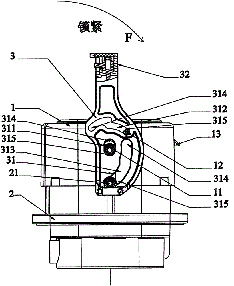
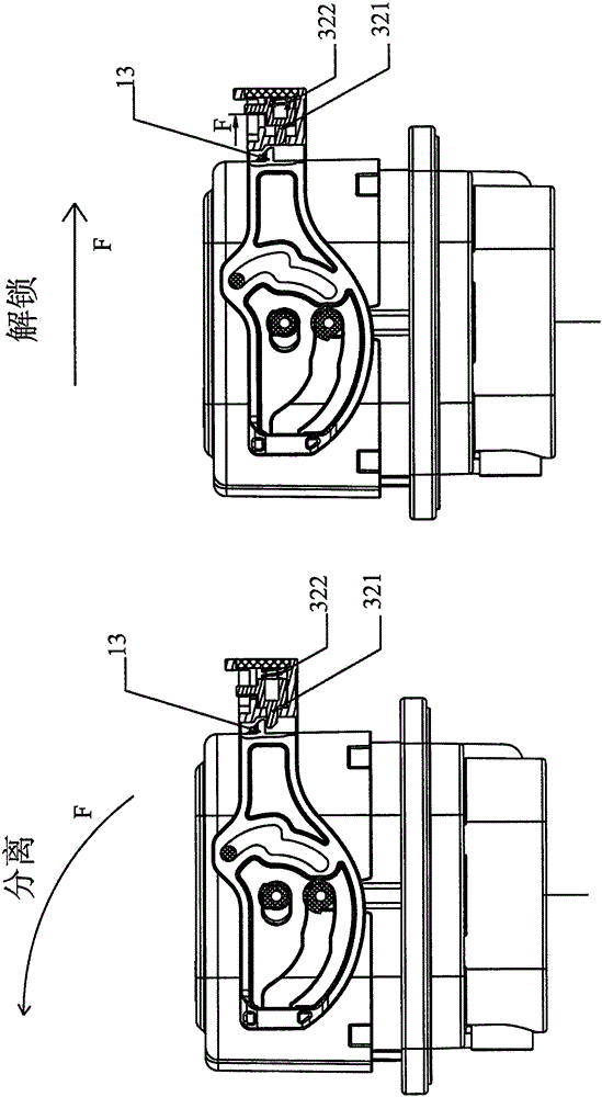
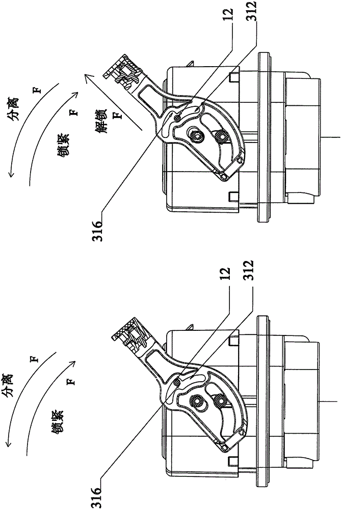
[0026] as attached figure 1 To attach image 3 As shown, a new electric vehicle connector plug step-by-step locking device includes a plug part 1, a socket part 2 and a handle part 3. The plug part 1 includes a plug first guide post 11, a plug second guide post 12 and a plug part card Buckle 13, the socket part 2 includes a socket guide post 21, the handle part 3 includes a track 31 and a handle buckle assembly 32, the track 31 includes a first track 311, a second track 312 and a third track 313, and the track 31 includes a head End 314 and trailing end 315 , second track 312 includes offset sub-track 316 .

[0027] The plug part 1 is inserted into the socket part 2 and locked by the handle part 3 .

[0028] The first plug guide post 11 and the second plug guide post 12 are both arranged on the outside o...


PUM


Abstract

The invention relates to the field of locking devices of connectors, in particular to a step-by-step locking device for a plug of a novel electric car connector. The step-by-step locking device comprises a plug component, a socket component and a handle component, wherein a first guide post of the plug, a second guide post of the pug and a socket guide post respectively slide to the head ends of a first track, a second track and a third track in a locking state; the first guide post of the plug, the second guide post of the plug and the socket guide post respectively slide to the tail ends of the first track, the second track and the third track in an unlocking state; and when the locking state is converted into the unlocking state, particularly, the second guide post of the plug slides to the middle part from the head end of the second track, the second guide post of the plug is blocked at the upper end of an offset sub-rail, and the handle component exerts up-inclined external force, so that the second guide post of the plug moves to the lower end of the offset sub-rail, and further slides to the tail end. The step-by-step locking device has the beneficial effect that a user does not need to directly contact an outer cover of the connector when locking or unlocking the outer cover, so that the electric potential safety hazard when an electric car is charged is removed.

Description

technical field [0001] The invention relates to the field of locking devices for connectors, in particular to a novel electric vehicle connector plug step-by-step locking device. Background technique [0002] At present, with the huge demand for new energy vehicles in the world, the field of electric vehicles is developing rapidly. It can be said that electric vehicles and related industries, such as electric stations, have a bright future in China. However, in the current situation, although the country has vigorously advocated it, and various enterprises have high popularity, a series of technical problems, such as the difficulty of charging, have become a bottleneck that restricts the entry of electric vehicles into ordinary people's homes in the short term. [0003] But charging safety is one of the issues limiting the development of rechargeable electric vehicles. [0004] At present, one of the commonly used charging protection measures is to install protective compon...

Claims


Application Information

Patent Timeline
IPC IPC(8): H01R13/629
Inventor 何桂元令狐云波林国军
Owner SHENZHEN BUSBAR SCI TECH DEV
Learn More